Nissan Versa (N17): Power supply and ground circuit
Diagnosis Procedure
Regarding Wiring Diagram information, refer to BCS "Wiring Diagram".
1.CHECK FUSES AND FUSIBLE LINK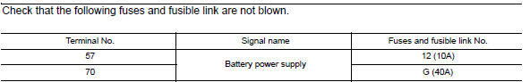
Is the fuse blown?
YES >> Replace the blown fuse or fusible link after repairing the affected circuit.
NO >> GO TO 2.
2.CHECK POWER SUPPLY CIRCUIT
1. Disconnect BCM connector M99.
2. Check voltage between BCM connector M99 and ground. 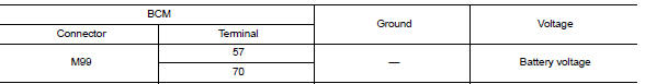
Is the inspection result normal?
YES >> GO TO 3.
NO >> Repair harness or connector.
3.CHECK GROUND CIRCUIT
Check continuity between BCM connector M99 and ground.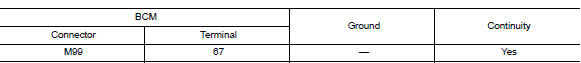
Is the inspection result normal?
YES >> Inspection End.
NO >> Repair harness or connector.
 B2562 Low voltage
Combination switch input circuit
Diagnosis Procedure Regarding Wiring Diagram information, refer to BCS "Wiring Diagram". 1.CHECK INPUT 1 - 5 CIRCUIT FOR OPEN 1. Turn ignition switch OFF. 2. Disconnect BCM and combinati ...
Other materials:
General maintenance
During the normal day-to-day operation of the
vehicle, general maintenance should be performed
regularly as prescribed in this section. If
you detect any unusual sounds, vibrations or
smells, be sure to check for the cause or have a
NISSAN dealer do it promptly. In addition, it is
recommended ...
Structure and operation
TRANSAXLE
TRANSAXLE : Cross-Sectional View
1. Converter housing 2. Oil pump 3. Counter drive gear
4. Control valve 5. Oil pan 6. Primary pulley
7. Steel belt 8. Secondary pulley 9. Planetary gear (auxiliary gearbox)
10. Side cover 11. Transaxle case 12. Differential case
13. Final gear ...
Categories
- Manuals Home
- Nissan Versa Owners Manual
- Nissan Versa Service Manual
- Video Guides
- Questions & Answers
- External Resources
- Latest Updates
- Most Popular
- Sitemap
- Search the site
- Privacy Policy
- Contact Us

0.0054