Nissan Versa (N17): Combination switch
Exploded View
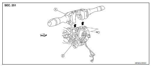
1. Combination switch 2. Combination switch harness connector  Front
Front
Removal and Installation
REMOVAL
1. Remove the steering wheel. Refer to ST "Removal and Installation".
2. Remove the steering column cover. Refer to IP "Removal and Installation".
3. Remove the combination switch screws.
4. Disconnect the harness connector from the combination switch.
5. Remove the combination switch by lifting upward.
INSTALLATION
Installation is in the reverse order of removal.
WITHOUT INTELLIGENT KEY SYSTEM
 BCM (Body control module)
Removal and Installation CAUTION: Before replacing BCM, perform "READ CONFIGURATION" to save or print current vehicle specification. Refer to BCS "ADDITIONAL SERVICE WHEN REPLACING CONTROL ...
Precautions
Precaution for Supplemental Restraint System (SRS) "AIR BAG" and "SEAT BELT PRE-TENSIONER" The Supplemental Restraint System such as "AIR BAG" and "SEAT BELT PRE-TENSIONER", us ...
Other materials:
Shift lock system
Component Function Check
1.CHECK SHIFT LOCK OPERATION (BRAKE PEDAL RELEASED)
Ignition switch ON.
Attempt to shift selector lever to any position other than "P" position
with brake pedal released.
Can the selector lever be shifted?
YES >> Go to TM "Diagnosis Procedure".
...
Performance test
Inspection
INSPECTION PROCEDURE
Connect recovery/recycling/recharging equipment (for HFC-134a) or
manifold gauge.
Start the engine, and set to the following condition.
Test condition &n ...
Categories
- Manuals Home
- Nissan Versa Owners Manual
- Nissan Versa Service Manual
- Video Guides
- Questions & Answers
- External Resources
- Latest Updates
- Most Popular
- Sitemap
- Search the site
- Privacy Policy
- Contact Us

0.0071