Nissan Versa (N17): BCM Branch line circuit
Diagnosis Procedure
1.CHECK CONNECTOR
1. Turn the ignition switch OFF.
2. Disconnect the battery cable from the negative terminal.
3. Check the terminals and connectors of the BCM for damage, bend and loose connection (unit side and connector side).
Is the inspection result normal?
YES >> GO TO 2.
NO >> Repair the terminal and connector.
2.CHECK HARNESS FOR OPEN CIRCUIT
1. Disconnect the connector of BCM.
2. Check the resistance between the BCM harness connector terminals.
- Models with Intelligent Key system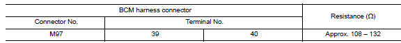
- Models without Intelligent Key system 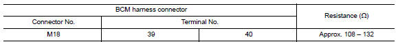
Is the measurement value within the specification?
YES >> GO TO 3.
NO >> Repair the BCM branch line.
3.CHECK POWER SUPPLY AND GROUND CIRCUIT
Check the power supply and the ground circuit of the BCM. Refer to the following.
- Models with Intelligent Key system: BCS"Diagnosis Procedure"
- Models without Intelligent Key system: BCS"Diagnosis Procedure"
Is the inspection result normal?
YES (Present error)>>Replace the BCM. Refer to the following.
- Models with Intelligent Key system: BCS "Removal and Installation"
- Models without Intelligent Key system: BCS"Removal and Installation"
YES (Past error)>>Error was detected in the BCM branch line.
NO >> Repair the power supply and the ground circuit.
 STRG Branch line circuit
Diagnosis Procedure 1.CHECK CONNECTOR 1. Turn the ignition switch OFF. 2. Disconnect the battery cable from the negative terminal. 3. Check the terminals and connectors of the steering angle sen ...
CAN Communication circuit
Diagnosis Procedure 1.CONNECTOR INSPECTION 1. Turn the ignition switch OFF. 2. Disconnect the battery cable from the negative terminal. 3. Disconnect all the unit connectors on CAN communication ...
Other materials:
Instrument panel
1. Headlight/turn signal switch/fog light
switch (if so equipped)
2. Driver's supplemental air bag (P. 1-39)
Horn
3. Meters and gauges. Warning and indicator lights
4. Wiper and washer switch
5. Vents
6. Rear window defroster switch
7. Front passenger air bag status light
8. Hazard warn ...
Torsion bar
TORSION BAR : Removal and Installation
REMOVAL
Remove torsion bar clamp.
Support trunk lid with a suitable tool.
WARNING:
Bodily injury may occur if trunk lid is not supported properly when removing the
torsion bars.
3. Apply a torsion bar wrench (A) to ...
Categories
- Manuals Home
- Nissan Versa Owners Manual
- Nissan Versa Service Manual
- Video Guides
- Questions & Answers
- External Resources
- Latest Updates
- Most Popular
- Sitemap
- Search the site
- Privacy Policy
- Contact Us

0.0051