Nissan Versa (N17): Engine protection control at low engine oil pressure
Engine protection control at low engine oil pressure : system diagram
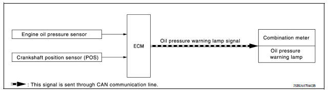
Engine protection control at low engine oil pressure : system description
INPUT/OUTPUT SIGNAL CHART
| Sensor | Input signal to ECM | ECM function | Actuator |
| Engine oil pressure sensor | Engine pressure | Engine protection control - Oil pressure warning lamp signal |
Combination meter - Oil pressure warning lamp |
| Crankshaft position sensor (POS) | Engine speed |
SYSTEM DESCRIPTION
- The engine protection control at low engine oil pressure warns the driver of a decrease in engine oil pressure by the oil pressure warning lamp a before the engine becomes damaged.
- When detecting a decrease in engine oil pressure at an engine speed less than 1,000 rpm, ECM transmits an oil pressure warning lamp signal to the combination meter. The combination meter turns ON the oil pressure warning lamp, according to the signal.
| Decrease in engine oil pressure | Engine speed | Combination meter |
| Oil pressure warning lamp | ||
| Detection | Less than 1,000 rpm | ON* |
| 1,000 rpm or more | ON |
 Exhaust valve timing control
Exhaust valve timing control : system diagram Exhaust valve timing control : system description INPUT/OUTPUT SIGNAL CHART Sensor Input signal to ECM ECM function Actuator ...
Fuel filler cap warning system
FUEL FILLER CAP WARNING SYSTEM : System Diagram FUEL FILLER CAP WARNING SYSTEM : System Description INPUT/OUTPUT SIGNAL CHART Input Unit/Sensor Input signal to ECM ECM function ...
Other materials:
Instrument panel
1. Headlight/turn signal switch/fog light
switch (if so equipped)
2. Driver's supplemental air bag (P. 1-39)
Horn
3. Meters and gauges. Warning and indicator lights
4. Wiper and washer switch
5. Vents
6. Rear window defroster switch
7. Front passenger air bag status light
8. Hazard warn ...
Steering wheel
Tilt operation
Push the lock lever 1 down and adjust the
steering wheel up or down 2 to the desired
position.
Pull the lock lever 1 up to lock the steering
wheel in place.
WARNING
Do not adjust the steering wheel while
driving. You could lose control of your
vehicle and cause an accid ...
Categories
- Manuals Home
- Nissan Versa Owners Manual
- Nissan Versa Service Manual
- Video Guides
- Questions & Answers
- External Resources
- Latest Updates
- Most Popular
- Sitemap
- Search the site
- Privacy Policy
- Contact Us

0.0059