Nissan Versa (N17): Fuel filler cap warning system
FUEL FILLER CAP WARNING SYSTEM : System Diagram
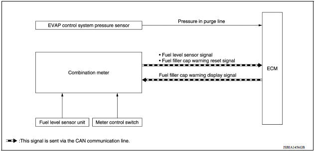
FUEL FILLER CAP WARNING SYSTEM : System Description
INPUT/OUTPUT SIGNAL CHART
Input
| Unit/Sensor | Input signal to ECM | ECM function |
| EVAP control system pressure sensor | Pressure in purge line | Fuel filler cap warning control |
| Combination meter | Fuel level sensor signal* | |
| Fuel filler cap warning reset signal* |
*: This signal is sent to the ECM via the CAN communication line.
Output
| Unit | Output signal | Actuato |
| ECM | Fuel filler cap warning display signal* | Combination meter |
*: This signal is sent to the ECM via the CAN communication line.
SYSTEM DESCRIPTION
The fuel filler cap warning system alerts the driver to the prevention of the fuel filler being left uncapped and malfunction occurrences after refueling, by turning ON the fuel filler cap warning display on the combination meter.
ECM judges a refueled state, based on a fuel level signal transmitted from the combination meter.
When a very small leak is detected through the EVAP leak diagnosis performed after judging the refueled state, ECM transmits a fuel filler cap warning display signal (request for display ON) to the combination meter via CAN communication.
When receiving the signal, the combination meter turns ON the fuel filler cap warning display.
CAUTION:
Check fuel filler cap installation condition when the fuel filler cap warning display turns ON.
Reset Operation
The fuel filler cap warning lamp tunes OFF, according to any condition listed below:
- Reset operation is performed by operating the odo/trip meter switch
(TYPE A) or
 switch (TYPE B) on
the
combination meter. Check the vehicle type to confirm the service information
in MWI section.
switch (TYPE B) on
the
combination meter. Check the vehicle type to confirm the service information
in MWI section.
- When the reset operation is performed, the combination meter transmits a fuel filler cap warning reset signal to ECM via CAN communication. ECM transmits a fuel filler cap warning display signal (request for display OFF) to the combination meter via CAN communication. When receiving the signal, the combination meter turns OFF the fuel filler cap warning display.
- EVAP leak diagnosis result is normal.
- Fuel refilled.
- DTC erased by using CONSULT.
NOTE:
MIL turns ON if a malfunction is detected in leak diagnosis results again at the trip after the fuel filler cap warning display turns ON/OFF.
 Engine protection control at low engine oil pressure
Engine protection control at low engine oil pressure : system diagram Engine protection control at low engine oil pressure : system description INPUT/OUTPUT SIGNAL CHART Sensor Inpu ...
Automatic speed control device (ASCD)
Automatic speed control device (ascd) : system diagram NOTE: Transmission range switch and TCM is also for A/T models. Automatic speed control device (ascd) : system description INPUT/OUTPUT ...
Other materials:
P072E Stuck in 3GR
DTC Logic
DTC DETECTION LOGIC
DTC
Trouble diagnosis name
DTC detection condition
Possible causes
P072E
Stuck in Gear 3
The following diagnosis conditions
are met and the detection
conditions continue for 0.5 seconds
or more.- Diagnosis condition
- Shifti ...
Output speed sensor
Exploded View
1. Output speed sensor 2. O-ring 3. Transaxle assembly
Front
Removal and Installation
REMOVAL
Remove the front LH wheel and tire.
Disconnect the harness connector from output speed sensor.
Remove the output speed sensor.
Remove the O-ring from the output speed sens ...
Categories
- Manuals Home
- Nissan Versa Owners Manual
- Nissan Versa Service Manual
- Video Guides
- Questions & Answers
- External Resources
- Latest Updates
- Most Popular
- Sitemap
- Search the site
- Privacy Policy
- Contact Us

0.005