Nissan Versa (N17): Power supply and ground circuit
Audio unit
AUDIO UNIT : Diagnosis Procedure
Regarding Wiring Diagram information, refer to AV"Wiring Diagram".
1.CHECK FUSE
Check that the following fuses are not blown.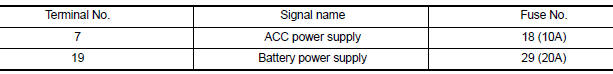
Are the fuses blown?
YES >> Replace the blown fuse after repairing the affected circuit.
NO >> GO TO 2.
2.CHECK POWER SUPPLY CIRCUIT
1. Turn ignition switch OFF.
2. Disconnect audio unit connector M44.
3. Check voltage between audio unit connector M44 and ground.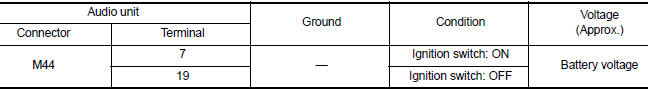
Is the inspection result normal?
YES >> GO TO 3.
NO >> Repair or replace harness or connectors.
3.CHECK GROUND CIRCUIT
1. Turn ignition switch OFF.
2. Disconnect audio unit connector M45.
3. Check continuity between audio unit connector M45 and ground.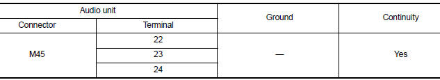
Is the inspection result normal?
YES >> Inspection End.
NO >> Repair or replace harness or connectors.
Bluetooth control unit
BLUETOOTH CONTROL UNIT : Diagnosis Procedure
Regarding Wiring Diagram information, refer to AV "Wiring Diagram".
1.CHECK FUSE
Check that the following fuses are not blown.
Are the fuses blown?
YES >> Replace the blown fuse after repairing the affected circuit.
NO >> GO TO 2.
2.CHECK POWER SUPPLY CIRCUIT
1. Turn ignition switch OFF.
2. Disconnect Bluetooth control unit connector B33.
3. Check voltage between Bluetooth control unit connector B33 and ground.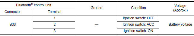
Is the inspection result normal?
YES >> GO TO 3.
NO >> Repair or replace harness or connectors.
3.CHECK GROUND CIRCUIT
1. Turn ignition switch OFF.
2. Check continuity between Bluetooth control unit connector B33 and ground.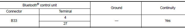
Is the inspection result normal?
YES >> Inspection End.
NO >> Repair or replace harness or connectors.
 Diagnosis and repair workflow
Work Flow OVERALL SEQUENCE DETAILED FLOW 1.GET INFORMATION FOR SYMPTOM Get detailed information from the customer about the symptom (the condition and the environment when the incident/malf ...
Front door speaker
Diagnosis Procedure Regarding Wiring Diagram information, refer to AV "Wiring Diagram". 1.CONNECTOR CHECK Check the audio unit and speaker connectors for the following: Proper conne ...
Other materials:
Cleaning exterior
In order to maintain the appearance of your vehicle,
it is important to take proper care of it.
To protect the paint surfaces, please wash your
vehicle as soon as you can:
After a rainfall to prevent possible damage
from acid rain.
After driving on coastal roads.
When contaminants suc ...
Idle air volume learning
Description
Idle Air Volume Learning is a function of ECM to learn the idle air volume
that keeps each engine idle speed
within the specific range. It must be performed under any of the following
conditions:
Each time electric throttle control actuator or ECM is replaced.
Idle speed or ...
Categories
- Manuals Home
- Nissan Versa Owners Manual
- Nissan Versa Service Manual
- Video Guides
- Questions & Answers
- External Resources
- Latest Updates
- Most Popular
- Sitemap
- Search the site
- Privacy Policy
- Contact Us

0.0066