Nissan Versa (N17): Bluetooth voice signal circuit
Diagnosis Procedure
Regarding Wiring Diagram information, refer to AV "Wiring Diagram".
1.CHECK BLUETOOTH VOICE SIGNAL CIRCUIT CONTINUITY
1. Turn ignition switch OFF.
2. Disconnect audio unit connector M47 and Bluetooth control unit connector B33.
3. Check continuity between audio unit connector M47 and Bluetooth control
unit connector B33.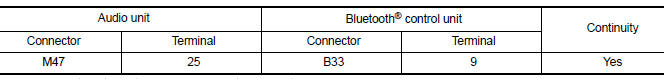
4. Check continuity between audio unit connector M47 and ground.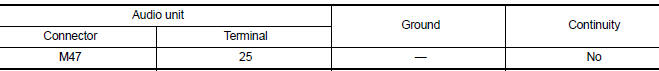
Is inspection result normal?
YES >> GO TO 2.
NO >> Repair or replace harness or connectors.
2.CHECK BLUETOOTH VOICE SIGNAL GROUND CIRCUIT CONTINUITY
Check continuity between audio unit connector M47 and Bluetooth control unit
connector B33.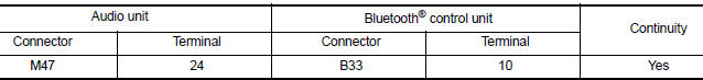
Is inspection result normal?
YES >> GO TO 3.
NO >> Repair or replace harness or connectors.
3.CHECK BLUETOOTH VOICE SIGNAL
1. Connect audio unit connector M47 and Bluetooth control unit connector B33.
2. Turn ignition switch to ACC.
3. Press  switch.
4. Check signal between the terminals of audio unit connector M47.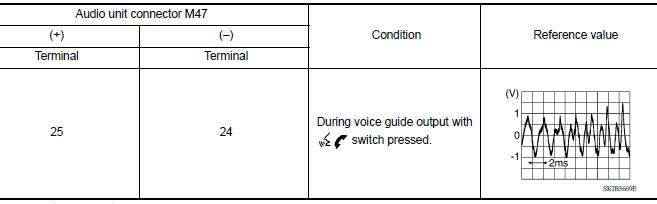
Is the inspection result normal?
YES >> Replace Bluetooth control unit. Refer to AV "Removal and Installation".
NO >> Replace audio unit. Refer to AV "Removal and Installation".
 Rear door speaker
Diagnosis Procedure Regarding Wiring Diagram information, refer to AV "Wiring Diagram". 1.CONNECTOR CHECK Check the audio unit and speaker connectors for the following: Proper conne ...
Bluetooth control signal circuit
Diagnosis Procedure Regarding Wiring Diagram information, refer to AV "Wiring Diagram". 1.CHECK CONTROL SIGNAL CIRCUIT CONTINUITY 1. Turn ignition switch OFF. 2. Disconnect Bluetooth con ...
Other materials:
Fuel efficient driving tips
Follow these easy-to-use Fuel Efficient Driving
Tips to help you achieve the most fuel economy
from your vehicle.
1. Use Smooth Accelerator and Brake
Pedal Application
Avoid rapid starts and stops.
Use smooth, gentle accelerator and
brake application whenever possible.
Maintain constan ...
A/C Indicator
Diagnosis Procedure
Regarding Wiring Diagram information, refer to HAC "Wiring Diagram" or HAC
"Wiring Diagram".
1.CHECK A/C INDICATOR POWER SUPPLY
Turn ignition switch ON.
Check voltage between front air control harness connector and ground.
Is the inspec ...
Categories
- Manuals Home
- Nissan Versa Owners Manual
- Nissan Versa Service Manual
- Video Guides
- Questions & Answers
- External Resources
- Latest Updates
- Most Popular
- Sitemap
- Search the site
- Privacy Policy
- Contact Us

0.0045