Nissan Versa (N17): Brake pedal
Inspection and Adjustment
INSPECTION
Brake Pedal Height
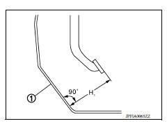
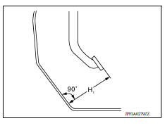
Check the height (H1) between the dash lower panel (1) and the brake pedal upper surface.
(H1) : Refer to BR "Brake Pedal".
CAUTION: Remove the floor trim.
Stop Lamp Switch
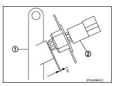
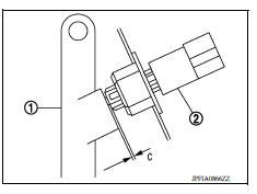
Check the clearance (C) among the brake pedal lever (1) and the stop lamp switch (2) threaded end.
(C) : Refer to BR "Brake Pedal".
CAUTION: The stop lamp must turn off when the brake pedal is released.
ASCD Cancel Switch
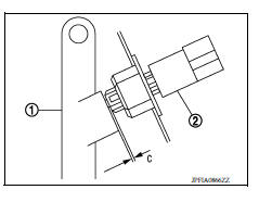
Check the clearance (C) among the brake pedal lever (1) and the ASCD cancel switch (2) threaded end.
(C) : Refer to BR "Brake Pedal".
CAUTION: The stop lamp must turn off when the brake pedal is released.
Brake Pedal Play
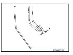
Press the brake pedal. Check the brake pedal play (A) (stroke until fluid pressure occurs).
(A) : Refer to BR "Brake Pedal".
Depressed Brake Pedal Height
Check the height between the dash lower panel (1) and the brake pedal upper surface (H2) when depressing the brake pedal at 490 N (50 kg-f, 110 lb-f) while turning engine ON.
(H2) : Refer to BR "Brake Pedal".
CAUTION: Remove the floor trim.

ADJUSTMENT
Brake Pedal Height
- Remove instrument lower panel LH. Refer to IP "Removal and Installation".
- Disconnect the harness connector from stop lamp switch.
- Loosen the stop lamp switch 45 counterclockwise.
- Adjust the brake pedal height with the following procedure.
a. Loosen the input rod lock nut (1).
CAUTION: The threaded end of the input rod (2) must project to the inner side (L) of the clevis (3).
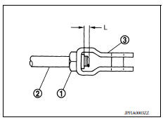
b. Rotate the input rod, adjust the brake pedal to the specified height (H1).
(H1) : Refer to BR "Brake Pedal".
c. Tighten the lock nut. Refer to BR "Exploded View".
5. Check the brake pedal play.
Stop Lamp Switch
- Remove instrument lower panel LH. Refer to IP "Removal and Installation".
- Disconnect the harness connector from stop lamp switch.
- Loosen the stop lamp switch 45 counterclockwise.
- Press-fit the stop lamp switch (2) until the stop lamp switch hits the brake pedal lever (1) 45 clockwise while pulling the brake pedal pad slightly.
CAUTION:
- The clearance (C) between the brake pedal lever and stop lamp switch threaded and must be the specified value.
(C) : Refer to BR "Brake Pedal".
- The stop lamp must be turned off when the brake pedal is released.
ASCD Cancel Switch
- Remove instrument lower panel LH. Refer to IP "Removal and Installation".
- Disconnect the harness connector from ASCD cancel switch.
- Loosen the stop lamp switch 45 counterclockwise.
- Press-fit the ASCD cancel switch (2) until the ASCD cancel switch hits the brake pedal lever (1) 45 clockwise while pulling the brake pedal pad slightly.
CAUTION:
- The clearance (C) between the brake pedal lever and ASCD cancel switch threaded and must be the specified value.
(C) : Refer to BR "Brake Pedal".
- The stop lamp must be turned off when the brake pedal is released.
 Precautions
Other materials:
Event Data Recorders (EDR)
This vehicle is equipped with an Event Data Recorder
(EDR). The main purpose of an EDR is to
record, in certain crash or near crash-like situations,
such as an air bag deployment or hitting a
road obstacle, data that will assist in understanding
how a vehicle's systems performed. The EDR
is de ...
Diagnosis system [abs actuator
and electric unit (control unit)]
CONSULT Function (ABS)
APPLICATION ITEMS
CONSULT can display each diagnostic item using the following direct
diagnostic modes.
ECU IDENTIFICATION
ABS actuator and electric unit (control unit) part number is displayed.
SELF DIAGNOSTIC RESULT
Operation Procedure
Before p ...
Categories
- Manuals Home
- Nissan Versa Owners Manual
- Nissan Versa Service Manual
- Video Guides
- Questions & Answers
- External Resources
- Latest Updates
- Most Popular
- Sitemap
- Search the site
- Privacy Policy
- Contact Us

0.0049