Nissan Versa (N17): C1116 Stop lamp switch
DTC Logic
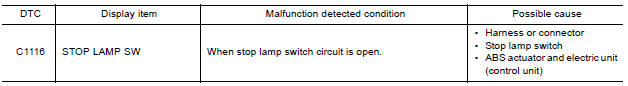
DTC DETECTION LOGIC
DTC CONFIRMATION PROCEDURE
1.CHECK SELF-DIAGNOSIS RESULTS
Check the self-diagnosis results.

Is above displayed on the self-diagnosis display?
YES >> Proceed to diagnosis procedure. Refer to BRC "Diagnosis Procedure".
NO >> Inspection End.
Diagnosis Procedure
Regarding Wiring Diagram information, refer to BRC "Wiring Diagram".
1.CONNECTOR INSPECTION
- Disconnect stop lamp switch connector and ABS actuator and electric unit (control unit) connector.
- Check terminals for deformation, disconnection, looseness or damage.
Is the inspection result normal?
YES >> GO TO 2
NO >> Repair or replace as necessary.
2.CHECK STOP LAMP SWITCH CIRCUIT
- Connect stop lamp switch connector.
- Check voltage between ABS actuator and electric unit (control unit)
connector E33 terminal 30 and
ground.
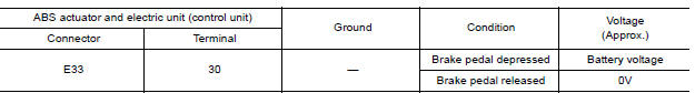
Is the inspection result normal?
YES >> Replace ABS actuator and electric unit (control unit). Refer to BRC "Removal and Installation".
NO >> GO TO 3
3.CHECK STOP LAMP SWITCH CIRCUIT FOR OPEN
- Disconnect stop lamp switch connector.
- Check continuity between ABS actuator and electric unit (control unit)
connector E33 terminal 30 and stop
lamp switch connector E13 (with CVT) or E57 (with M/T) terminal 2.
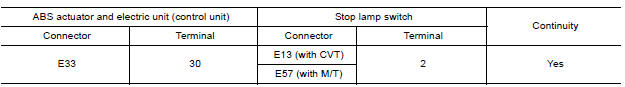
Is the inspection result normal?
YES >> GO TO 4.
NO >> Repair or replace as necessary.
4.CHECK STOP LAMP SWITCH CIRCUIT FOR SHORT
Check continuity between ABS actuator and electric unit (control unit)
connector E33 terminal 30 and ground.
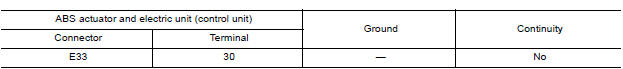
Is the inspection result normal?
YES >> Replace stop lamp switch.
NO >> Repair harness or connectors.
 C1115 ABS Sensor [abnormal signal]
Other materials:
Meters and gauges
Type A (if so equipped)
1. Tachometer
2. Speedometer
3. Fuel gauge
4. Odometer
Twin trip odometer
Trip computer
5. Continuously Variable Transmission
(CVT) position indicator (if so equipped)
Automatic Transmission (A/T) position
indicator (if so equipped)
6. Instrument brightness con ...
Hazard warning flasher switch
Push the switch on to warn other drivers when
you must stop or park under emergency conditions.
All turn signal lights flash.
WARNING
If stopping for an emergency, be sure to
move the vehicle well off the road.
Do not use the hazard warning flashers
while moving on the highway unl ...
Categories
- Manuals Home
- Nissan Versa Owners Manual
- Nissan Versa Service Manual
- Video Guides
- Questions & Answers
- External Resources
- Latest Updates
- Most Popular
- Sitemap
- Search the site
- Privacy Policy
- Contact Us

0.0193