
Nissan Versa (N17): EPS System
EPS SYSTEM : System Description
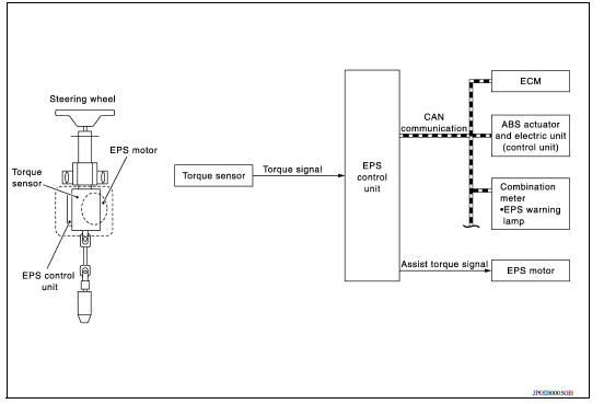
- EPS control unit performs an arithmetical operation on data, such as steering wheel turning force (sensor signal) from the torque sensor, vehicle speed signal, etc. Then it generates an optimum assist torque signal to the EPS motor according to the driving condition.
- In case of an error in the electrical system, the fail-safe function stops output signals to the EPS motor. Refer to STC "EPS SYSTEM : Fail-Safe".
- EPS control unit decreases the output signal to EPS motor while extremely using the power steering function (e.g., full steering) consecutively for protecting EPS motor and EPS control unit (Overload protection control). Refer to STC "EPS SYSTEM : Protection Function".
- Extensive steering at low speed will cause the ECU and MOTOR to heat up, once temperature reaches critical point ECU will reduce current to reduce heat up. System will recover as temperature lowers (reduced or no assistance).
SYSTEM DIAGRAM
INPUT/OUTPUT SIGNAL
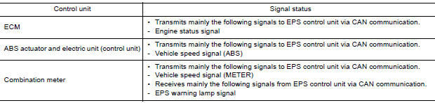
Communicates the signal from each control unit via CAN communication.
EPS WARNING LAMP INDICATION
- Turn ON when there is a malfunction in EPS system. If indicates that fail-safe mode is engaged and enters a manual steering state (Control turning force steering wheel becomes heavy).
- Also turns ON when ignition switch is turned ON, for purpose of lamp check. Turns OFF after the engine starts, if system is normal.

CAUTION: EPS warning lamp also turns ON due to data reception error, CAN communication error etc.
EPS SYSTEM : Fail-Safe
- If any malfunction occurs in the system and control unit detects the malfunction, EPS warning lamp in combination meter turns ON to indicate system malfunction.
- When EPS warning lamp is ON, the system enters into a manual steering state. (Steering wheel turning force becomes heavy.)
- Under abnormal vehicle speed signal conditions, vehicle speed is judged as constant.
EPS SYSTEM : Protection Function
EPS control unit decreases the output signal to EPS motor while extremely using the power steering function (e.g., full steering) consecutively for protecting EPS motor and EPS control unit (Overload protection control).
While activating overload protection control, the assist torque gradually decreases, and the steering wheel turning force becomes heavy. The normal assist torque reactivates by no steering.
 Precautions
Diagnosis system (EPS control unit)
CONSULT Function FUNCTION CONSULT can display each diagnostic item using the diagnostic test modes shown following. *: The following diagnosis information is erased by erasing. ...
Other materials:
EVAP canister vent control valve
Exploded View
1. EVAP canister 2. O-ring 3. EVAP canister vent control valve
4. EVAP canister vent control valve hose
Removal and Installation
NOTE:
The EVAP canister vent control valve can be removed without removing the EVAP
canister.
REMOVAL
Remove the EVAP canister protector cov ...
U0073 Communication bus a off
DTC Logic
DTC
Trouble diagnosis name
DTC detecting condition
Possible causes
U0073
Control Module Communication
Bus "A" Off
When the ignition switch is ON,
TCM detects a bus-off error
continuously for 2 seconds or
more.
Harness or connector
(CA ...
Categories
- Manuals Home
- Nissan Versa Owners Manual
- Nissan Versa Service Manual
- Video Guides
- Questions & Answers
- External Resources
- Latest Updates
- Most Popular
- Sitemap
- Search the site
- Privacy Policy
- Contact Us

0.0065