Nissan Versa (N17): C1120, C1122, C1124, C1126 ABS In valve system
DTC Logic
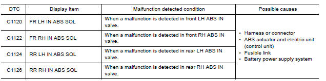
DTC DETECTION LOGIC
DTC CONFIRMATION PROCEDURE
1.CHECK SELF DIAGNOSTIC RESULT
With CONSULT.
- Turn ignition switch ON.
- Perform self diagnostic result.
Is DTC C1120, C1122, C1124 or C1126 detected?
YES >> Proceed to diagnosis procedure. Refer to BRC "Diagnosis Procedure".
NO >> Inspection End.
Diagnosis Procedure
Regarding Wiring Diagram information, refer to BRC "Wiring Diagram".
1.CONNECTOR INSPECTION
- Turn ignition switch OFF.
- Disconnect ABS actuator and electric unit (control unit) connector.
- Check connector and terminals for deformation, disconnection, looseness or damage.
Is the inspection result normal?
YES >> GO TO 2
NO >> Repair or replace as necessary.
2.CHECK ABS ACTUATOR AND ELECTRIC UNIT (CONTROL UNIT) BATTERY POWER SUPPLY
Check voltage between ABS actuator and electric unit (control unit) connector
E33 terminal 25 and ground. 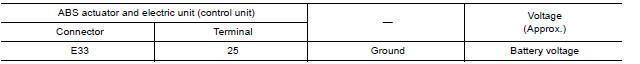
Is the inspection result normal?
YES >> GO TO 3.
NO >> Repair or replace malfunctioning components.
3.CHECK ABS ACTUATOR AND ELECTRIC UNIT (CONTROL UNIT) GROUND CIRCUIT
Check continuity between ABS actuator and electric unit (control unit)
connector E33 terminals 13, 38 and
ground. 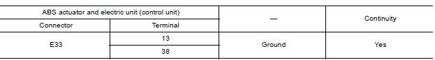
Is the inspection result normal?
YES >> Replace ABS actuator and electric unit (control unit). Refer to BRC "Removal and Installation".
NO >> Repair or replace malfunctioning components.
 C1116 Stop lamp switch
Other materials:
Cylinder block
Exploded View
1. Crankshaft position sensor cover 2. Crankshaft position sensor (POS) 3.
Oring
4. Drain plug 5. Cylinder block 6. Oil level gauge
7. Oil level gauge guide 8. Oring 9. Knock sensor 10. Oil temperature sensor
11. Oil pressure sensor 12. Oil jet
13. Top ring 14. Second ring ...
Engine protection control at low engine oil pressure
Engine protection control at low engine oil pressure : system diagram
Engine protection control at low engine
oil pressure : system description
INPUT/OUTPUT SIGNAL CHART
Sensor
Input signal to ECM
ECM function
Actuator
Engine oil pressure sensor
Engine pressure
...
Categories
- Manuals Home
- Nissan Versa Owners Manual
- Nissan Versa Service Manual
- Video Guides
- Questions & Answers
- External Resources
- Latest Updates
- Most Popular
- Sitemap
- Search the site
- Privacy Policy
- Contact Us

0.0054