Nissan Versa (N17): Clutch disc and clutch cover
Exploded View
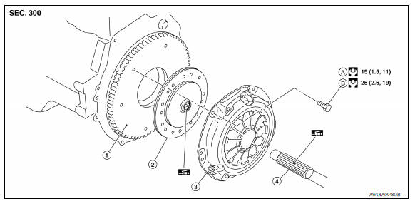
1. Flywheel 2. Clutch disc 3. Clutch cover
4. Input shaft A. First step B. Final step
 : Apply lithium-based grease
including molybdenum disulphide.
: Apply lithium-based grease
including molybdenum disulphide.
Removal and Installation
CAUTION:
- Do not reuse CSC (concentric slave cylinder). CSC slides back to the original position every time when removing transaxle assembly. At this time, dust on the sliding parts may damage the seal of CSC and may cause clutch fluid leakage.
- Do not allow any grease to contact the clutch disc facing, pressure plate surface and flywheel surface.
- Do not clean clutch disc using solvent.
REMOVAL
- Remove transaxle assembly. Refer to TM, "Removal and Installation".
- Loosen clutch cover bolts evenly. Then remove clutch cover and clutch disc.
INSTALLATION
- Clean clutch disc and input shaft splines to remove grease and dust caused by abrasion.
- Apply recommended grease to clutch disc and input shaft splines.
CAUTION: Be sure to apply grease to the points specified. Otherwise, noise, poor disengagement, or damage to the clutch may result. Excessive grease may cause slip or shudder. If grease adheres to seal of CSC, it may cause clutch fluid leakage. Wipe off excess grease. Wipe off any grease oozing from the parts.
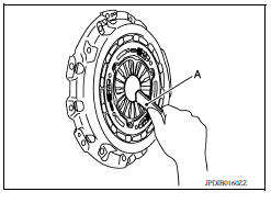
- Install clutch disc, using suitable tool (A).
- Install clutch cover and then temporarily tighten clutch cover bolts.
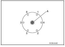
- Tighten clutch cover bolts to the specified torque evenly in two steps in the numerical order as shown.
- Install transaxle assembly. Refer to TM, "Removal and Installation".
Inspection
INSPECTION AFTER REMOVAL
Clutch Disc
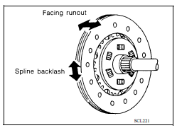
- Measure clutch facing runout. If it is outside the specification, replace clutch disc.
Runout limit/diameter of the area to be measured : Refer to CL, "Clutch Disc".
- Measure spline backlash at outer edge of clutch disc. If it is outside the specification, replace clutch disc.
Maximum allowable spline backlash (at outer edge of disc) : Refer to CL, "Clutch Disc".
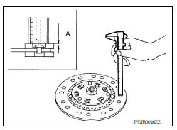
- Measure the depth (A) to clutch disc facing rivet heads, using suitable tool. If it exceeds the allowable wear limit, replace clutch disc.
Facing wear limit (depth to the rivet head) (A) : Refer to CL, "Clutch Disc".
Clutch Cover
- Check clutch cover thrust ring for wear or damage. If wear or damage is found, replace clutch cover.
NOTE:
- Worn thrust ring will generate a beating noise when tapped at the rivet using suitable tool.
- Broken thrust ring will make a clinking sound when cover is shaken up and down.
- If a trace of burn or discoloration is found on the clutch cover pressure plate to clutch disc contact surface, repair the surface with sandpaper. If surface is damaged or distorted, replace clutch cover.
INSPECTION AFTER INSTALLATION
Clutch Cover
Check diaphragm spring levers for unevenness with the clutch cover installed on the engine. If they exceed the tolerance, adjust diaphragm spring lever height, using Tool (A).
Tolerance for diaphragm spring lever unevenness : Refer to CL-21, "Clutch Cover".
Tool number : ST20050240 ( - )
 CSC (Concentric slave cylinder)
Exploded View 1. Transaxle assembly 2. CSC (concentric slave cylinder) Removal and Installation CAUTION: Do not reuse CSC (concentric slave cylinder). CSC slides back to the original po ...
Service data and specifications
(SDS)
General Specifications Engine type HR16DE Type of clutch control Hydraulic Clutch disc Facing size (Outer dia. × Inner dia. × Thickness) 200 &time ...
Other materials:
U1001 CAN comm circuit
Description
CAN (Controller Area Network) is a serial communication line for real time
application. It is an onvehicle multiplex
communication line with high data communication speed and excellent error
detection ability. Many electronic
control units are equipped onto a vehicle, and each con ...
G Sensor
Exploded View
1. G sensor
Front
Removal and Installation
CAUTION:
Do not drop or strike G sensor, because it may be damaged by
impact.
Do not use a power tool.
REMOVAL
Disconnect the battery negative terminal. Refer to PG "Removal and
Installation".
Remov ...
Categories
- Manuals Home
- Nissan Versa Owners Manual
- Nissan Versa Service Manual
- Video Guides
- Questions & Answers
- External Resources
- Latest Updates
- Most Popular
- Sitemap
- Search the site
- Privacy Policy
- Contact Us

0.0075