Nissan Versa (N17): Clutch pedal
Exploded View
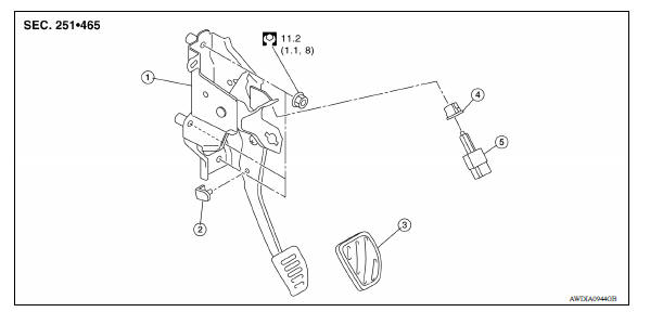
1. Clutch pedal 2. Pedal stopper rubber 3. Pedal pad 4. Clip 5. Clutch interlock switch
Removal and Installation
REMOVAL
- Remove the instrument lower panel LH. Refer to IP, "Removal and Installation".
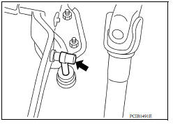
- Disconnect master cylinder rod end from clutch pedal.
- Disconnect clutch interlock switch connector.
- Remove harness clip from clutch pedal.
- Remove clutch pedal nuts and remove clutch pedal from the vehicle.
- Remove pedal pad from clutch pedal.
- Remove clutch interlock switch and clip from clutch pedal.
- Remove pedal stopper rubber from clutch pedal, using a suitable tool.
INSTALLATION
Installation is in the reverse order of removal.
CAUTION: Press master cylinder rod end into clutch pedal until it stops.
Inspection and Adjustment
INSPECTION AFTER REMOVAL
- Check clutch pedal for bend, damage, or a cracked weld. If bend, damage, or a cracked weld is found, replace clutch pedal.
- Check pedal stopper rubber. If damage or deformation is found, replace pedal stopper rubber.
- Check pedal pad. If wear or damage is found, replace pedal pad.
INSPECTION AND ADJUSTMENT AFTER INSTALLATION
Inspect the clutch interlock switch position and adjust as necessary. Refer to CL, "Inspection and Adjustment".
 Clutch fluid
Clutch master cylinder
Exploded View 1. Reservoir hose 2. Master cylinder Removal and Installation CAUTION: Do not spill clutch fluid onto painted surfaces. If fluid spills, wipe up immediately and wash the ...
Other materials:
Fuel filler cap warning system
FUEL FILLER CAP WARNING SYSTEM : System Diagram
FUEL FILLER CAP WARNING SYSTEM : System Description
INPUT/OUTPUT SIGNAL CHART
Input
Unit/Sensor
Input signal to ECM
ECM function
EVAP control system pressure sensor
Pressure in purge line
Fuel filler cap warning cont ...
Id registration procedure
Description
This procedure must be performed after replacing wheels, transmitters or the
BCM, or rotating wheels.
Work Procedure
NOTE:
The Signal Tech II Tool (J-50190) can be used to perform the following
functions. Refer to the Signal Tech II
User Guide for additional information.
Ac ...
Categories
- Manuals Home
- Nissan Versa Owners Manual
- Nissan Versa Service Manual
- Video Guides
- Questions & Answers
- External Resources
- Latest Updates
- Most Popular
- Sitemap
- Search the site
- Privacy Policy
- Contact Us

0.0061