Nissan Versa (N17): Clutch piping
Exploded View
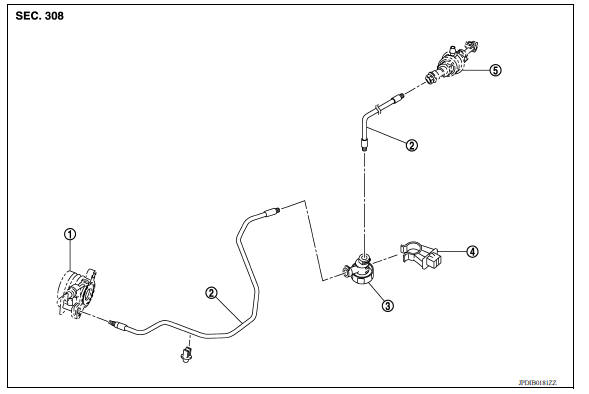
1. CSC (Concentric Slave Cylinder) 2. Clutch tube 3. Clutch damper 4. Bracket 5. Master cylinder
Hydraulic Layout

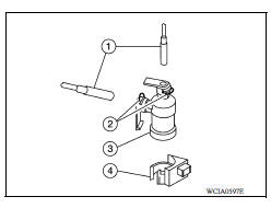
1. Clutch tube 2. Lock pin 3. CSC (concentric slave cylinder) 4. Clutch damper 5. Master cylinder 6. Clutch pedal
Removal and Installation
CAUTION: Do not spill clutch fluid onto painted surfaces. If fluid spills, wipe up immediately and wash the affected area with water.
NOTE: When removing components such as hoses, tubes/lines, etc., cap or plug openings to prevent fluid from spilling.
REMOVAL
- Remove the battery. Refer to PG, "Removal and Installation".
- Use one of the following methods to remove hose from clutch master cylinder.
- Drain clutch fluid from reservoir tank and remove hose. Refer to CL, "Draining".
- Remove hose from clutch master cylinder.
- Remove clutch tube lock pin from clutch master cylinder.
- Remove clutch tube lock pin at clutch housing.
- Remove clutch tube lock pins (2) from clutch damper (3).
- Remove clutch tube (1) from clutch damper (3).
- Remove clutch damper (3) from bracket (4).
INSTALLATION
Installation is in the reverse order of removal.
CAUTION: Do not damage clutch tube.
- Insert each clutch tube into the CSC bleeding connector, the clutch damper connector, and the clutch master cylinder connector until it contacts the end of each connector.
- Install each lock pin into the clutch damper connector and the clutch master cylinder connector until it contacts the end of each connector.
- After installation, bleed the air from the clutch hydraulic system. Refer to CL, "Air Bleeding".
Inspection and Adjustment
INSPECTION AFTER REMOVAL
- Check the clutch tube for cracks and damage. If the clutch tube has cracks or damage, replace it with a new one.
- Check the O-ring of the clutch tube for cracks and damage. If the O-ring of the clutch tube has cracks or damage, replace clutch tube with a new one.
- Check the clutch damper for cracks and damage. If the clutch damper has cracks or damage, replace it with a new one.
INSPECTION AFTER INSTALLATION
Check for fluid leakage and check the fluid level. Refer to CL, "Inspection".
 Clutch master cylinder
Exploded View 1. Reservoir hose 2. Master cylinder Removal and Installation CAUTION: Do not spill clutch fluid onto painted surfaces. If fluid spills, wipe up immediately and wash the ...
CSC (Concentric slave cylinder)
Exploded View 1. Transaxle assembly 2. CSC (concentric slave cylinder) Removal and Installation CAUTION: Do not reuse CSC (concentric slave cylinder). CSC slides back to the original po ...
Other materials:
EVAP canister vent control valve
Exploded View
1. EVAP canister 2. O-ring 3. EVAP canister vent control valve
4. EVAP canister vent control valve hose
Removal and Installation
NOTE:
The EVAP canister vent control valve can be removed without removing the EVAP
canister.
REMOVAL
Remove the EVAP canister protector cov ...
A/C Indicator
Diagnosis Procedure
Regarding Wiring Diagram information, refer to HAC "Wiring Diagram" or HAC
"Wiring Diagram".
1.CHECK A/C INDICATOR POWER SUPPLY
Turn ignition switch ON.
Check voltage between front air control harness connector and ground.
Is the inspec ...
Categories
- Manuals Home
- Nissan Versa Owners Manual
- Nissan Versa Service Manual
- Video Guides
- Questions & Answers
- External Resources
- Latest Updates
- Most Popular
- Sitemap
- Search the site
- Privacy Policy
- Contact Us

0.0047