Nissan Versa (N17): Remote keyless entry receiver
Component Function Check
1.CHECK FUNCTION
- Select "INTELLIGENT KEY" of "BCM" using CONSULT.
- Select "RKE OPE COUN1" in "DATA MONITOR" mode.
- Check that the function operates normally according to the following
conditions.

Is the inspection result normal?
YES >> Remote keyless entry receiver is OK.
NO for USA >>Refer to DLK "Diagnosis Procedure (For USA)".
NO for Canada>>Refer to DLK "Diagnosis Procedure (For Canada)".
Diagnosis Procedure (For USA)
Regarding Wiring Diagram information, refer to DLK"INTELLIGENT KEY SYSTEM : Wiring Diagram".
1.CHECK REMOTE KEYLESS ENTRY RECEIVER OUTPUT SIGNAL
- Turn ignition switch OFF.
- Check signal between BCM harness connector and ground using
oscilloscope.
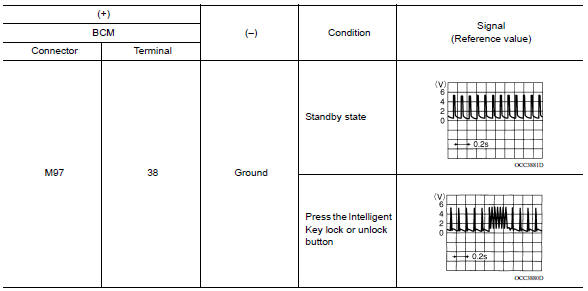
Is the inspection result normal?
YES >> Replace BCM. Refer to BCS "Removal and Installation".
NO >> GO TO 2.
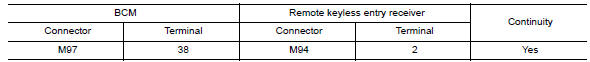
2.CHECK REMOTE KEYLESS ENTRY RECEIVER CIRCUIT 1
- Disconnect BCM and remote keyless entry receiver connectors.
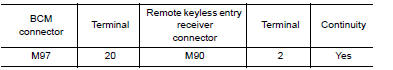
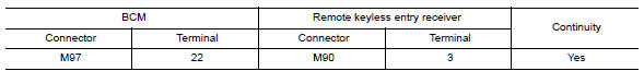
- Check continuity between BCM harness connector and remote keyless entry
receiver harness connector.
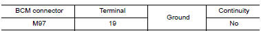
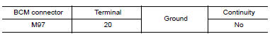
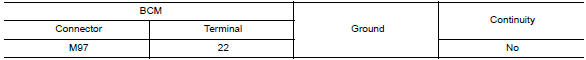
- Check continuity between BCM harness connector and ground.
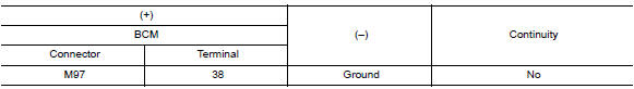
Is the inspection result normal?
YES >> GO TO 3.
NO >> Repair or replace harness.
3.CHECK REMOTE KEYLESS ENTRY RECEIVER POWER SUPPLY
Check voltage between remote keyless entry receiver harness connector and
ground. 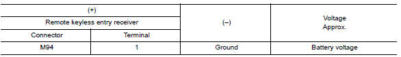
Is the inspection result normal?
YES >> GO TO 4.
NO-1 >> Check 10A fuse No. 14 [located in fuse block J/B].
NO-2 >> Repair or replace harness between BCM and 10A fuse No. 14.
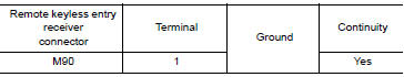
4.CHECK REMOTE KEYLESS ENTRY RECEIVER GROUND CIRCUIT
Check continuity between remote keyless entry receiver harness connector and
ground. 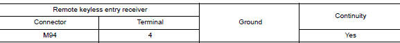
Is the inspection result normal?
YES >> Replace remote keyless entry receiver. Refer to DLK "Removal and Installation".
NO >> Repair or replace harness.
Diagnosis Procedure (For Canada)
Regarding Wiring Diagram information, refer to DLK "INTELLIGENT KEY SYSTEM : Wiring Diagram".
1.CHECK REMOTE KEYLESS ENTRY RECEIVER OUTPUT SIGNAL
- Turn ignition switch OFF.
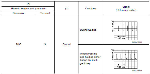
- Check signal between remote keyless entry receiver connector and ground
with oscilloscope.
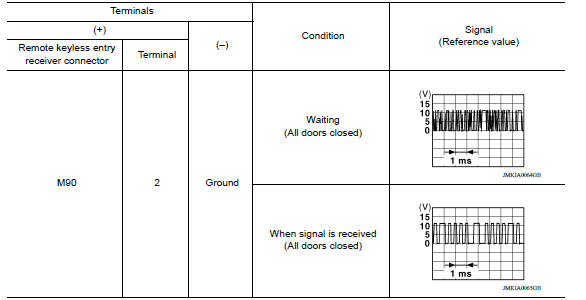
Is the inspection result normal?
YES >> GO TO 7
NO >> GO TO 2
2.CHECK REMOTE KEYLESS ENTRY RECEIVER POWER SUPPLY
- Disconnect remote keyless entry receiver connector.
- Check signal between remote keyless entry receiver connector and ground
with oscilloscope.
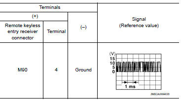
Is the inspection result normal?
YES >> GO TO 4
NO >> GO TO 3
3.CHECK REMOTE KEYLESS ENTRY RECEIVER CIRCUIT 1
- Disconnect BCM connector.
- Check continuity between BCM connector and remote keyless entry receiver
connector.
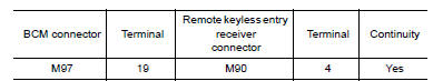
- Check continuity between BCM connector and ground.
Is the inspection result normal?
YES >> Reconnect BCM, GO TO 4
NO >> Repair or replace harness between BCM and remote keyless entry receiver.
4.CHECK REMOTE KEYLESS ENTRY RECEIVER GROUND CIRCUIT
Check continuity between remote keyless entry receiver connector and ground.
Is the inspection result normal?
YES >> GO TO 6
NO >> GO TO 5
5.CHECK REMOTE KEYLESS ENTRY RECEIVER CIRCUIT 2
Check continuity between BCM connector and remote keyless entry receiver
connector. 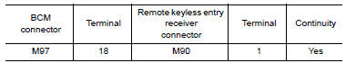
Is the inspection result normal?
YES >> GO TO 6
NO >> Repair or replace harness between BCM and remote keyless entry receiver.
6.CHECK REMOTE KEYLESS ENTRY RECEIVER CIRCUIT 3
- Check continuity between BCM connector and remote keyless entry receiver
connector.
- Check continuity between BCM connector and ground.
Is the inspection result normal?
YES >> GO TO 7
NO >> Repair or replace harness between BCM and remote keyless entry.
7.CHECK REMOTE KEYLESS ENTRY RECEIVER RSSI SIGNAL CIRCUIT
- Disconnect BCM connector.
- Check continuity between BCM harness connector and remote keyless entry
receiver harness connector.
- Check continuity between BCM harness connector and ground.
Is the inspection result normal?
YES >> GO TO 8
NO >> Repair or replace harness between BCM and remote keyless entry.
8.CHECK REMOTE KEYLESS ENTRY RECEIVER RSSI SIGNAL
- Reconnect remote keyless entry receiver connector.
- Check signal between remote keyless entry receiver harness connector and
ground using oscilloscope.
Is the inspection result normal?
YES >> GO TO 9.
NO >> Replace remote keyless entry receiver. Refer to DLK "Removal and Installation".
9.CHECK INTERMITTENT INCIDENT
Refer to GI "Intermittent Incident".
>> Inspection End.
 Key warning lamp
Component Function Check 1.CHECK FUNCTION Select INTELLIGENT KEY of BCM using CONSULT. Select INDICATOR in ACTIVE TEST mode. Touch KEY IND or KEY ON to check that it works normally. Is the ...
Shift P Warning lamp
Component Function Check 1.CHECK FUNCTION Select INTELLIGENT KEY of BCM using CONSULT. Select LCD in ACTIVE TEST mode. Touch SET P to check that it works normally. Is the inspection resu ...
Other materials:
Clutch pedal
Exploded View
1. Clutch pedal 2. Pedal stopper rubber 3. Pedal pad
4. Clip 5. Clutch interlock switch
Removal and Installation
REMOVAL
Remove the instrument lower panel LH. Refer to IP, "Removal and
Installation".
Disconnect master cylinder rod end from clutch pedal.
D ...
Lock-up control
LOCK-UP CONTROL : System Description
SYSTEM DIAGRAM
DESCRIPTION
Controls for improvement of the transmission efficiency by engaging the
torque converter clutch in the
torque converter and eliminating slip of the converter. Achieves comfortable
driving with slip control of the
t ...
Categories
- Manuals Home
- Nissan Versa Owners Manual
- Nissan Versa Service Manual
- Video Guides
- Questions & Answers
- External Resources
- Latest Updates
- Most Popular
- Sitemap
- Search the site
- Privacy Policy
- Contact Us

0.0078