Nissan Versa (N17): Door switch
Description
Detects door open/close condition.
Component Function Check
1.CHECK FUNCTION
With CONSULT
Check door switches DOOR SW-DR, DOOR SW-AS, DOOR SW-RL, DOOR SW-RR in Data
Monitor mode
with CONSULT. 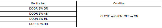
Is the inspection result normal?
YES >> Door switch is OK.
NO >> Refer to DLK "Diagnosis Procedure".
Diagnosis Procedure
Regarding Wiring Diagram information, refer to DLK "Wiring Diagram".
1.CHECK DOOR SWITCH INPUT SIGNAL
- Turn ignition switch OFF.
- Check signal between BCM connector and ground with oscilloscope.
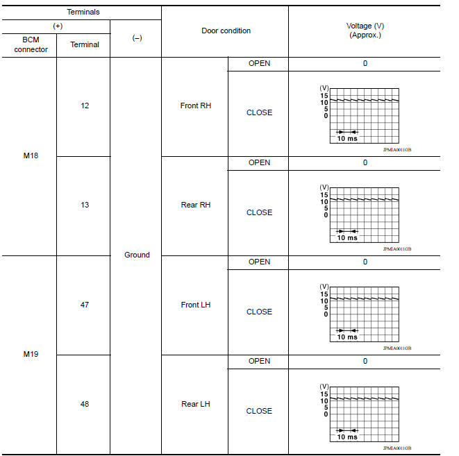
Is the inspection result normal?
YES >> GO TO 4
NO >> GO TO 2
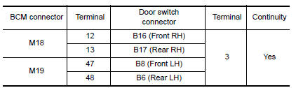
2.CHECK DOOR SWITCH CIRCUIT
- Disconnect BCM connector.
- Check continuity between BCM connector and door switch connector.
- Check continuity between BCM connector and ground.
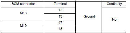
Is the inspection result normal?
YES >> GO TO 3
NO >> Repair or replace harness between BCM and door switch.
3.CHECK DOOR SWITCH
Refer to DLK "Component Inspection".
Is the inspection result normal?
YES >> GO TO 4
NO >> Replace malfunctioning door switch.
4.CHECK INTERMITTENT INCIDENT
Refer to GI "Intermittent Incident".
>> Inspection End.
Component Inspection
1.CHECK DOOR SWITCH
- Turn ignition switch OFF.
- Disconnect door switch connector.
- Check door switch.
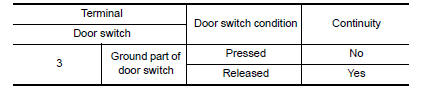
Is the inspection result normal?
YES >> Inspection End.
NO >> Replace malfunctioning door switch.
 Power supply and ground circuit
Diagnosis Procedure Regarding Wiring Diagram information, refer to BCS "Wiring Diagram". 1.CHECK FUSES AND FUSIBLE LINK Check that the following fuses and fusible link are not blown. ...

Other materials:
Compressor does not operate
Description
SYMPTOM
Compressor does not operate.
Diagnosis Procedure
NOTE:
Perform self-diagnosis with CONSULT before performing symptom
diagnosis. If any malfunction result or
DTC is detected, perform the corresponding diagnosis.
Check that refrigerant system is fully charged. If t ...
Center console lower
Removal and Installation
REMOVAL
Remove center console assembly. Refer to IP "Removal and Installation".
Remove center console lower.
a. Place front seats in a full rearward position.
b. Remove center console lower clips (A).
c. Disengage center console lower pawls and remove ...
Categories
- Manuals Home
- Nissan Versa Owners Manual
- Nissan Versa Service Manual
- Video Guides
- Questions & Answers
- External Resources
- Latest Updates
- Most Popular
- Sitemap
- Search the site
- Privacy Policy
- Contact Us

0.0124