Nissan Versa (N17): Interior room lamp control circuit
Description
Controls each interior room lamp (ground side) by PWM signal.
NOTE: PWM signal control period is approximately 250 Hz (in the gradual brightening/dimming).
Component Function Check
CAUTION: Before performing the diagnosis, check that the following are normal.
- Interior room lamp power supply
- Map lamp bulb
- Room lamp bulb
1.CHECK INTERIOR ROOM LAMP CONTROL FUNCTION
CONSULT
1. Switch the map lamp switch or interior room lamp switch to DOOR.
2. Turn ignition switch ON.
3. Select INT LAMP of BCM (INT LAMP) ACTIVE TEST item.
4. While operating the test items, check that each interior room lamp turns ON/OFF.
On : Interior room lamp gradual brightening
Off : Interior room lamp gradual dimming
Does the interior room lamp turns ON/OFF (gradual brightening/dimming)?
YES >> Interior room lamp control circuit is normal.
NO >> Refer to INL "Diagnosis Procedure".
Diagnosis Procedure
Regarding Wiring Diagram information, refer to INL "Wiring Diagram".
1.CHECK INTERIOR ROOM LAMP CONTROL OUTPUT
CONSULT
1. Turn ignition switch OFF.
2. Remove all the bulbs of map lamp and interior room lamp.
3. Turn ignition switch ON.
4. Select INT LAMP of BCM (INT LAMP) ACTIVE TEST item.
5. While operating the test item, check continuity between BCM harness
connector and ground.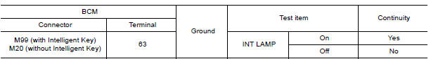
Is the inspection result normal?
YES >> GO TO 2.
Fixed ON>>GO TO 3.
Fixed OFF>>Replace BCM after making sure battery saver output/power supply circuit is not shorted to voltage.
Refer to BCS "Removal and Installation" (with Intelligent Key) or BCS "Removal and Installation" (without Intelligent Key).
2.CHECK INTERIOR ROOM LAMP CONTROL OPEN CIRCUIT
1. Turn ignition switch OFF.
2. Disconnect BCM connector and map lamp connector or interior room lamp connector.
3. Check continuity between BCM harness connector and map lamp harness connector or interior room lamp harness connector.
With map lamp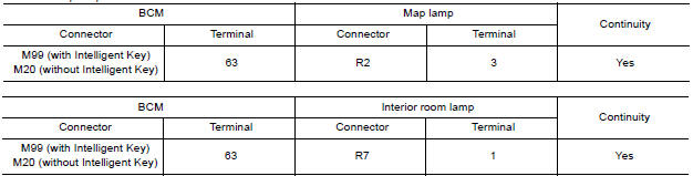
Is the inspection result normal?
YES >> Check that map lamp or interior room lamp has no internal open circuit.
NO >> Repair or replace harness or connector.
3.CHECK INTERIOR ROOM LAMP CONTROL SHORT CIRCUIT
1. Turn ignition switch OFF.
2. Disconnect BCM connector.
3. Check continuity between BCM harness connector and ground.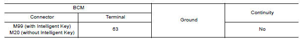
Is the inspection result normal?
YES >> Replace BCM after making sure battery saver output/power supply circuit is not shorted to voltage.
Refer to BCS "Removal and Installation" (with Intelligent Key) or BCS "Removal and Installation" (without Intelligent Key).
NO >> GO TO 4.
4.CHECK INTERIOR ROOM LAMP CONTROL SHORT CIRCUIT
1. Disconnect interior room lamp connector or map lamp connector.
2. Check continuity between BCM harness connector and ground.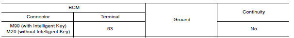
Is the inspection result normal?
YES >> Check that map lamp or interior room lamp has no internal short circuit.
NO >> Repair or replace harness or connector.
 Battery saver output/power supply
circuit
Battery saver output/power supply
circuit
Description Provides the battery saver output/power supply. Also cuts the power supply when the interior lamp battery saver is activated. ...
Trunk room lamp circuit
Description Controls the trunk room lamp (ground side) to turn the trunk room lamp ON and OFF. Component Function Check CAUTION: Before performing the diagnosis, check that the following is ...
Other materials:
Brake lining
BRAKE LINING : Inspection and Adjustment
INSPECTION
Brake Lining
Remove plug from back plate. Refer to BR "Exploded View".
Check brake lining wear thickness (A) from an inspection hole
on back plate. Check using a scale necessary.
(A) : Refer to BR "Rear Drum Brake&quo ...
EPS Warning lamp
Component Function Check
1.CHECK THE ILLUMINATION OF THE EPS WARNING LAMP
Check that the EPS warning lamp turns ON when ignition switch turns ON. Then,
EPS warning lamp turns
OFF after the engine is started.
Is the inspection result normal?
YES >> Inspection End.
NO >> Perform t ...
Categories
- Manuals Home
- Nissan Versa Owners Manual
- Nissan Versa Service Manual
- Video Guides
- Questions & Answers
- External Resources
- Latest Updates
- Most Popular
- Sitemap
- Search the site
- Privacy Policy
- Contact Us

0.0054