Nissan Versa (N17): Shift lock system
Component Function Check
1.CHECK SHIFT LOCK OPERATION (BRAKE PEDAL RELEASED)
- Ignition switch ON.
- Attempt to shift selector lever to any position other than Park with brake pedal released.
Can the selector lever be shifted?
YES >> Go to TM "Diagnosis Procedure".
NO >> GO TO 2.
2.CHECK SHIFT LOCK OPERATION (BRAKE PEDAL APPLIED)
Attempt to shift the selector lever to any position other than Park with brake pedal applied.
Can the selector lever be shifted?
YES >> Inspection End.
NO >> Go to TM "Diagnosis Procedure".
Diagnosis Procedure
1.CHECK STOP LAMP SWITCH
- Ignition switch ON.
- Check voltage between stop lamp switch connector E13 terminal 4 and
ground.
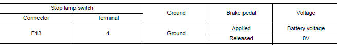
Is the inspection result normal?
YES >> GO TO 2.
NO >> GO TO 4.
2.CHECK A/T SHIFT SELECTOR
Check voltage between A/T shift selector connector M37 terminal 6 and ground. 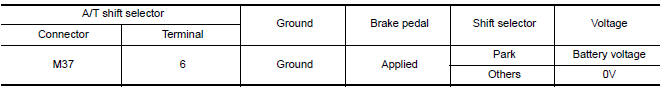
Is the inspection result normal?
YES >> GO TO 3.
NO >> GO TO 5.
3.CHECK GROUND CIRCUIT
- Ignition switch OFF.
- Disconnect A/T shift selector connector.
- Check continuity between A/T shift selector connector M37 terminal 6 and
ground.
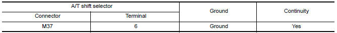
Is the inspection result normal?
YES >> Replace A/T shift selector. Refer to TM "Removal and Installation".
NO >> Repair or replace ground circuit.
4.CHECK STOP LAMP SWITCH POWER CIRCUIT
Check voltage between stop lamp switch connector E13 terminal 3 and ground. 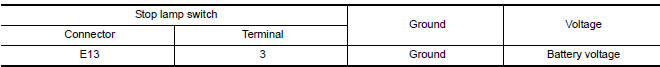
Is the inspection result normal?
YES >> Replace stop lamp switch.
NO >> Repair or replace power circuit.
5.CHECK A/T SHIFT SELECTOR POWER CIRCUIT
Check voltage between A/T shift selector connector M37 terminal 5 and ground. 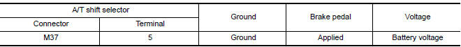
Is the inspection result normal?
YES >> Replace A/T shift selector. Refer to TM "Removal and Installation".
NO >> Repair or replace power circuit.
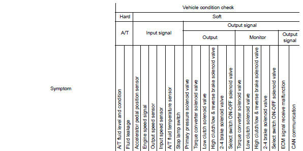
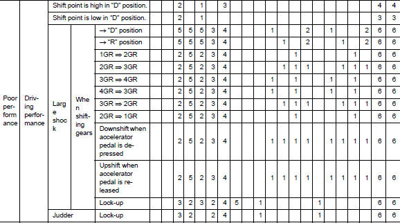
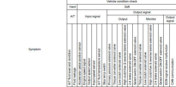
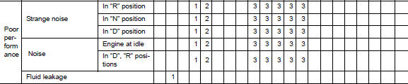
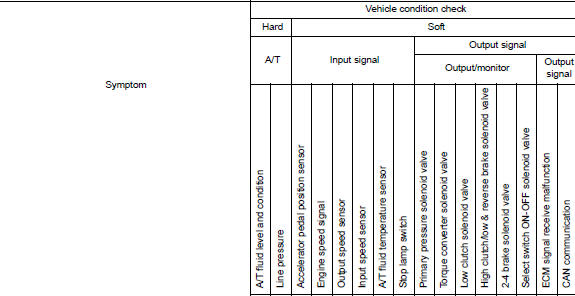
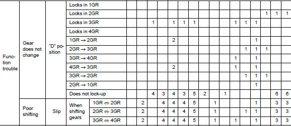
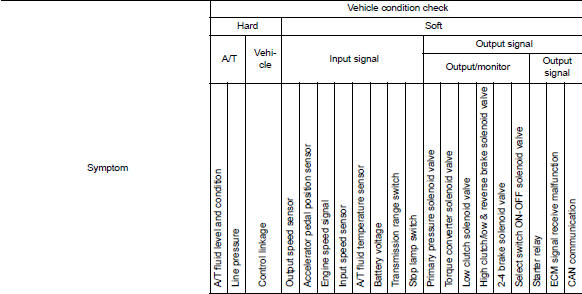
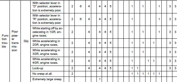
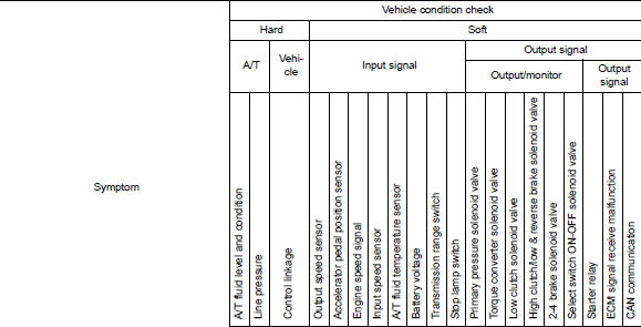
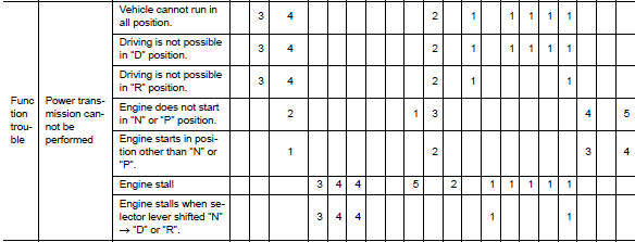
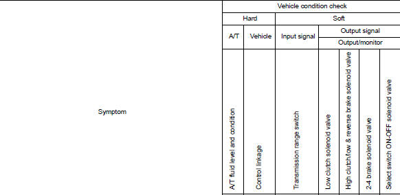
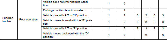
System symptom
Symptom Table
The diagnosis item numbers show the sequence for inspection. Inspect in order from item 1.
CAUTION: If any malfunction occurs in the RE4F03C transmission, replace the transaxle assembly.
 Shift position indicator circuit
Component Parts Function Inspection 1.CHECK SHIFT POSITION INDICATOR Start the engine. Shift the selector lever. Check that the selector lever position and the shift position indicator o ...
A/T Fluid
Inspection FLUID LEAKAGE Check transaxle surrounding area (oil seal and plug etc.)for fluid leakage. If anything is found, repair or replace damaged parts and adjust A/ T fluid level. Ref ...
Other materials:
Trunk lid
WARNING
Do not drive with the trunk lid open. This
could allow dangerous exhaust gases
to be drawn into the vehicle. For additional
information, refer to "Exhaust
gas (carbon monoxide)" in the "Starting
and driving" section of this manual.
Closely supervise children when they
are a ...
Installing front license plate
Use the following steps to mount the front license
plate:
Before mounting the license plate, confirm that
the following parts are enclosed in the plastic
bag:
License plate bracket
License plate bracket screws x 2
Screw grommets x 2
1. Hold the license plate bracket 1 and make
a ...
Categories
- Manuals Home
- Nissan Versa Owners Manual
- Nissan Versa Service Manual
- Video Guides
- Questions & Answers
- External Resources
- Latest Updates
- Most Popular
- Sitemap
- Search the site
- Privacy Policy
- Contact Us

0.0063