Nissan Versa (N17): Component parts
Component Parts Location
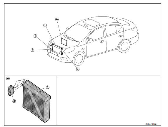
1. Condenser 2. Compressor 3. Refrigerant pressure sensor 4. Liquid tank 5. Evaporator 6. Expansion valve A. Built-in heater & cooling unit assembly
Component Description
| Component | Description |
| Evaporator | The mist form liquid refrigerant transforms to gas by evaporation by the air conveyed from blower motor. The air is cooled by the heat by evaporation. |
| Condenser | Cools refrigerant discharged from compressor, and transforms it to liquid refrigerant. |
| Compressor | Intakes, compresses, and discharges refrigerant, to circulate refrigerant inside the refrigerant cycle. |
| Refrigerant pressure sensor | Refer to HA "Removal and Installation". |
| Liquid tank | Eliminates foreign matter in refrigerant, and temporarily stores liquid refrigerant. |
| Expansion valve | Transforms high-pressure liquid refrigerant to mist form low-pressure liquid refrigerant by drawing function. |
 Preparation
Special Service Tool The actual shape of Kent-Moore tools may differ from those of special service tools illustrated here. HFC-134a (R-134a) Service Tool and Equipment Do not mix HFC-134a (R- ...
Refrigeration system
Refrigerant Cycle REFRIGERANT FLOW The refrigerant flows in the standard pattern, that is, through the compressor, the condenser with liquid tank, through the evaporator, and back to the compress ...
Other materials:
Bluetooth Hands-Free Phone System without Navigation System (Type B) (if so
equipped)
WARNING
Use a phone after stopping your vehicle
in a safe location. If you have to use a
phone while driving, exercise extreme
caution at all times so full attention may
be given to vehicle operation.
If you are unable to devote full attention
to vehicle operation while talking on
...
Preparation
Special Service Tools
The actual shapes of KentMoore tools may differ from those of special
service tools illustrated here.
Tool number
(KentMoore No.)
Tool name
Description
ST25051001
(J256951)
Oil pressure gauge &nbs ...
Categories
- Manuals Home
- Nissan Versa Owners Manual
- Nissan Versa Service Manual
- Video Guides
- Questions & Answers
- External Resources
- Latest Updates
- Most Popular
- Sitemap
- Search the site
- Privacy Policy
- Contact Us

0.0046