Nissan Versa (N17): Preparation
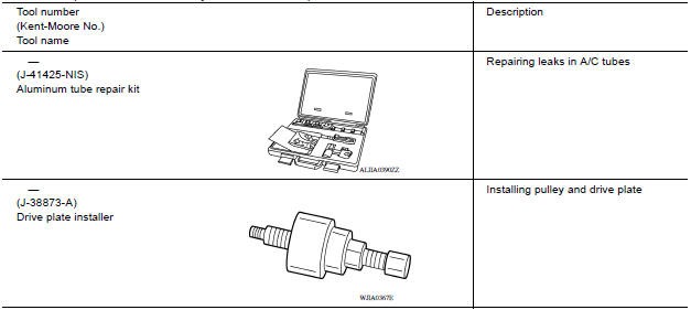
Special Service Tool
The actual shape of Kent-Moore tools may differ from those of special service tools illustrated here.
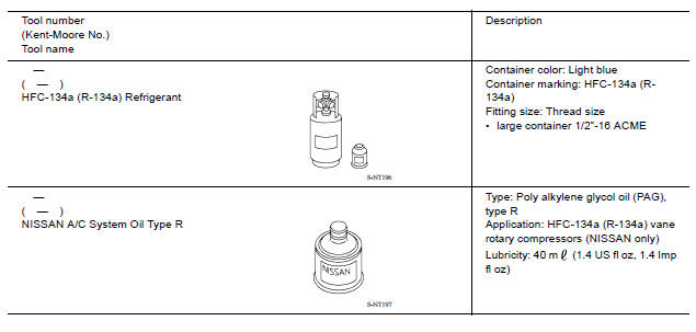
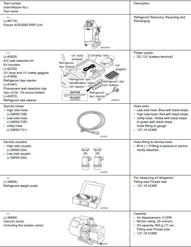
HFC-134a (R-134a) Service Tool and Equipment
Do not mix HFC-134a (R-134a) refrigerant and/or its specified oil with CFC-12 (R-12) refrigerant and/or its oil.
Separate and non-interchangeable service equipment must be used for handling each type of refrigerant/oil.
Refrigerant container fittings, service hose fittings and service equipment fittings (equipment which handles refrigerant and/or oil) are different between CFC-12 (R-12) and HFC-134a (R-134a). This is to avoid mixed use of the refrigerants/oil.
Adapters that convert one size fitting to another must not be used refrigerant/oil contamination will occur and compressor failure will result.
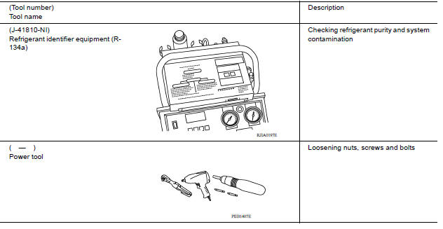
Commercial Service Tool
SYSTEM DESCRIPTION
 Precautions
Component parts
Component Parts Location 1. Condenser 2. Compressor 3. Refrigerant pressure sensor 4. Liquid tank 5. Evaporator 6. Expansion valve A. Built-in heater & cooling unit assembly Component Des ...
Other materials:
Vehicle Dynamic Control (VDC) off switch
The vehicle should be driven with the VDC system
on for most driving conditions.
If the vehicle is stuck in mud or snow, the VDC
system reduces the engine output to reduce
wheel spin. The engine speed will be reduced
even if the accelerator is depressed to the floor. If
maximum engine po ...
Shift change control
Shift change control : system diagram
Shift change control : system description
The clutch is controlled with the optimum timing and oil pressure by the
engine speed, engine torque information,
etc.
Shift Change System Diagram
*1: Full phase real-time feedback control monitors m ...
Categories
- Manuals Home
- Nissan Versa Owners Manual
- Nissan Versa Service Manual
- Video Guides
- Questions & Answers
- External Resources
- Latest Updates
- Most Popular
- Sitemap
- Search the site
- Privacy Policy
- Contact Us

0.0049