Nissan Versa (N17): CVT Control system
CVT Control system : system description
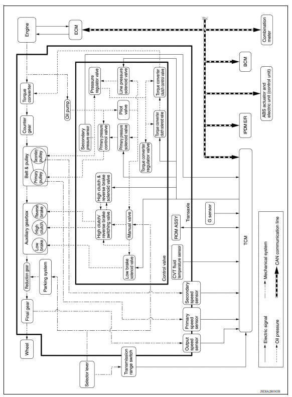
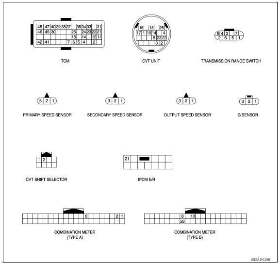
SYSTEM DIAGRAM
INPUT/OUTPUT SIGNAL TABLE
|
Sensor (or signal) |
 |
TCM function |
 |
Actuator |
|
|
|
SYSTEM DESCRIPTION
- CVT detects the vehicle driving status from switches, sensors and signals, and controls the vehicle so that the optimum shift position and shift timing may always be achieved. It also controls the vehicle to reduce shift and lockup shock, etc.
- Receives input signals from switches and sensors.
- Sends the output signal necessary for operation of solenoid valves, and evaluates the line pressure, shift timing, lockup operation, engine brake performance, etc.
- If a malfunction occurs on the electric system, activate the fail-safe mode only to drive the vehicle.
LIST OF CONTROL ITEMS AND INPUT/OUTPUT
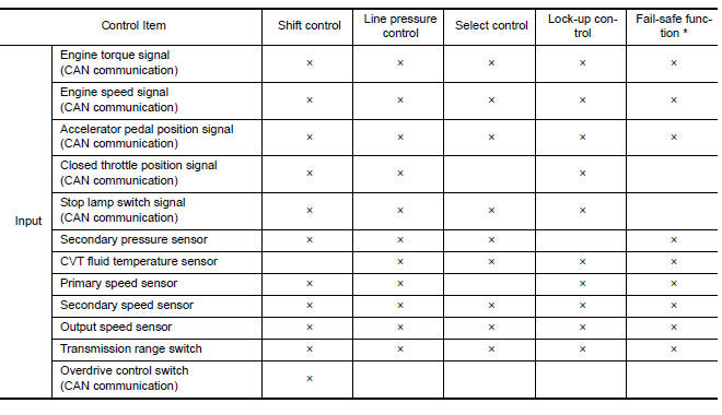
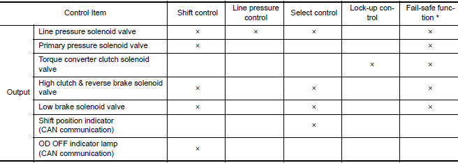
**: If these input/output signals show errors, TCM activates the fail-safe function.
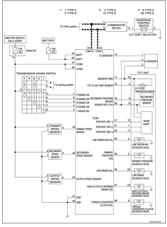
CVT CONTROL SYSTEM : Schematic
CVT Control system : fail-safe
TCM has a fail-safe mode. The mode functions so that operation can be continued even if the signal circuit of the main electronically controlled input/output parts is damaged.
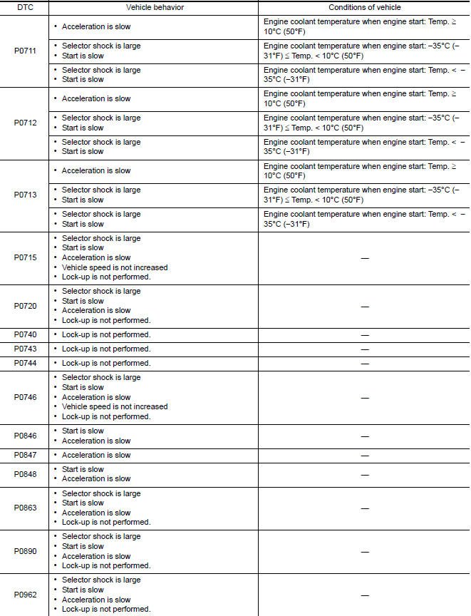
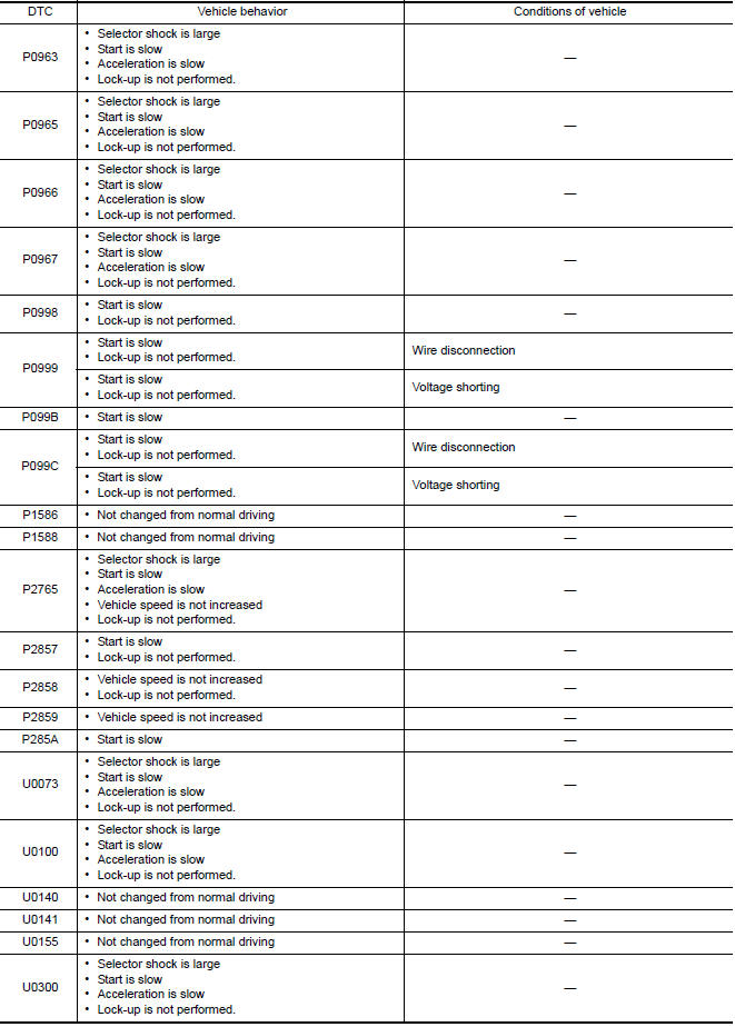
If the vehicle shows following behaviors including "poor acceleration", a malfunction of the applicable system is detected by TCM and the vehicle may be in a fail-safe mode. At this time, check the DTC code and perform inspection and repair according to the malfunction diagnosis procedures.
Fail-safe function
| DTC | Vehicle behavior | Conditions of vehicle |
| P062F |
|
- |
| P0705 |
|
- |
| P0706 |
|
- |

CVT Control system : protection control
The TCM becomes the protection control status temporarily to protect the safety when the safety of TCM and transmission is lost. It automatically returns to the normal status if the safety is secured.
The TCM has the following protection control.
CONTROL FOR WHEEL SPIN 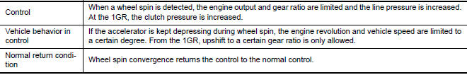
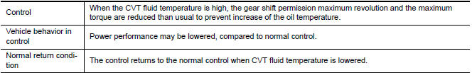
CONTROL WHEN FLUID TEMPERATURE IS HIGH
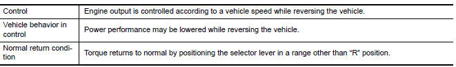
TORQUE IS REDUCED WHEN DRIVING WITH THE REVERSE GEAR
REVERSE PROHIBIT CONTROL 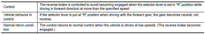
 Fluid cooler & fluid warmer system
FLUID COOLER & FLUID WARMER SYSTEM : System Description CVT FLUID COOLER SCHEMATIC COMPONENT DESCRIPTION CVT Oil Warmer The CVT oil warmer (1) is installed on the front part of trans ...
Line pressure control
LINE PRESSURE CONTROL : System Description SYSTEM DIAGRAM DESCRIPTION Highly accurate line pressure control (secondary pressure control) reduces friction for improvement of fuel economy. No ...
Other materials:
Head restraints/headrests
WARNING
Head restraints/headrests supplement
the other vehicle safety systems. They may
provide additional protection against injury
in certain rear end collisions. Adjustable
head restraints/headrests must be
adjusted properly, as specified in this section.
Check the adjustment after someo ...
O/D OFF indicator lamp
Component Function Check
1.CHECK O/D OFF INDICATOR LAMP FUNCTION
Check O/D OFF indicator lamp turns ON for approx. 2 seconds when ignition
switch turns ON.
Is the inspection results normal?
YES >> INSPECTION END
NO >> Go to TM "Diagnosis Procedure".
Diagnosis Procedur ...
Categories
- Manuals Home
- Nissan Versa Owners Manual
- Nissan Versa Service Manual
- Video Guides
- Questions & Answers
- External Resources
- Latest Updates
- Most Popular
- Sitemap
- Search the site
- Privacy Policy
- Contact Us

0.0056