Nissan Versa (N17): CVT Fluid cooler system
Cleaning
Whenever an automatic transaxle is repaired, overhauled, or replaced, the CVT fluid cooler mounted in the radiator must be inspected and cleaned.
Metal debris and friction material, if present, can be trapped or be deposited in the CVT fluid cooler. This debris can contaminate the newly serviced CVT or, in severe cases, can block or restrict the flow of CVT fluid.
In either case, malfunction of the newly serviced CVT may occur.
Debris, if present, may deposit as CVT fluid enters the cooler inlet. It will be necessary to back flush the cooler through the cooler outlet in order to flush out any built up debris.
CVT FLUID COOLER CLEANING PROCEDURE
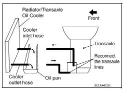
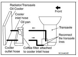
- Position an oil pan under the transaxle's inlet and outlet cooler hoses.
- Identify the inlet and outlet fluid cooler hoses.
- Disconnect the fluid cooler inlet and outlet rubber hoses from the
steel cooler tubes or bypass valve.
NOTE: Replace the cooler hoses if rubber material from the hose remains on the tube fitting.
- Allow any CVT fluid that remains in the cooler hoses to drain into the oil pan.
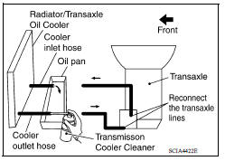
- Insert the extension adapter hose of a can of Transmission Cooler Cleaner (Nissan P/N 999MP-AM006) into the cooler outlet hose.
CAUTION:
- Wear safety glasses and rubber gloves when spraying the Transmission Cooler Cleaner.
- Spray Transmission Cooler Cleaner only with adequate ventilation.
- Avoid contact with eyes and skin.
- Never breath vapors or spray mist.
- Hold the hose and can as high as possible and spray Transmission Cooler Cleaner in a continuous stream into the cooler outlet hose until CVT fluid flows out of the cooler inlet hose for 5 seconds.
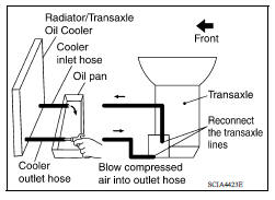
- Insert the tip of an air gun into the end of the cooler outlet hose.
- Wrap a shop rag around the air gun tip and end of the cooler outlet hose.
- Blow compressed air regulated to 5 to 9 kg/cm2 (70 to 130 psi) through the cooler outlet hose for 10 seconds to force out any remaining CVT fluid.
- Repeat steps 5 through 9 three additional times.
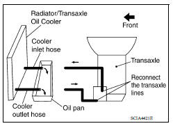
- Position an oil pan under the banjo bolts that connect the CVT fluid cooler steel lines to the transaxle.
- Remove the banjo bolts.
- Flush each steel line from the cooler side back toward the transaxle by spraying Transmission Cooler Cleaner in a continuous stream for 5 seconds.
- Blow compressed air regulated to 5 to 9 kg/cm2 (70 to 130 psi) through each steel line from the cooler side back toward the transaxle for 10 seconds to force out any remaining CVT fluid.
- Ensure all debris is removed from the steel cooler lines.
- Ensure all debris is removed from the banjo bolts and fittings.
- Perform "CVT FLUID COOLER DIAGNOSIS PROCEDURE".
CVT FLUID COOLER DIAGNOSIS PROCEDURE
NOTE: Insufficient cleaning of the cooler inlet hose exterior may lead to inaccurate debris identification.
- Position an oil pan under the transaxle's inlet and outlet cooler hoses.
- Clean the exterior and tip of the cooler inlet hose.
- Insert the extension adapter hose of a can of Transmission Cooler Cleaner (Nissan P/N 999MP-AM006) into the cooler outlet hose.
CAUTION:
- Wear safety glasses and rubber gloves when spraying the Transmission Cooler Cleaner.
- Spray Transmission Cooler Cleaner only with adequate ventilation.
- Avoid contact with eyes and skin.
- Never breath vapors or spray mist.
- Hold the hose and can as high as possible and spray Transmission Cooler Cleaner in a continuous stream into the cooler outlet hose until CVT fluid flows out of the cooler inlet hose for 5 seconds.
- Tie a common white, basket-type coffee filter to the end of the cooler inlet hose.
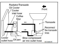
- Insert the tip of an air gun into the end of the cooler outlet hose.
- Wrap a shop rag around the air gun tip and end of cooler outlet hose.
- Blow compressed air regulated to 5 to 9 kg/cm2 (70 to 130 psi) through the cooler outlet hose to force any remaining CVT fluid into the coffee filter.
- Remove the coffee filter from the end of the cooler inlet hose.
- Perform "CVT FLUID COOLER INSPECTION PROCEDURE".
CVT FLUID COOLER INSPECTION PROCEDURE
1. Inspect the coffee filter for debris.
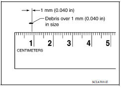
a. If small metal debris less than 1 mm (0.040 in) in size or metal powder is found in the coffee filter, this is normal. If normal debris is found, the CVT fluid cooler/radiator can be reused and the procedure is ended.
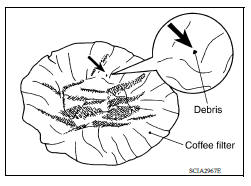
b. If one or more pieces of debris are found that are over 1 mm (0.040 in) in size and/or peeled clutch facing material is found in the coffee filter, the fluid cooler is not serviceable. The radiator/ fluid cooler must be replaced and the inspection procedure is ended.
CVT FLUID COOLER FINAL INSPECTION
After performing all procedures, ensure that all remaining oil is cleaned from all components.
 Calibration of G Sensor
Description TCM stores calibration data (inherent characteristic value) of G sensor to provide accurate control. Therefore, it is required to perform calibration of G sensor after the following wo ...
Stall test
Work Procedure INSPECTION Check the engine oil level. Replenish if necessary. Check for leak of the CVT fluid. Refer to TM "Inspection". Drive for about 10 minutes to warm up the v ...
Other materials:
Vehicle identification
Vehicle identification number (VIN) plate
The vehicle identification number (VIN) plate is
attached as shown. This number is the identification
for your vehicle and is used in the vehicle
registration.
Vehicle identification number (chassis number)
The vehicle identification number i ...
P0980 Shift solenoid C
DTC Logic
DTC DETECTION LOGIC
DTC
Trouble diagnosis name
DTC detection condition
Possible causes
P0980
Shift Solenoid C Control Circuit
High
The following diagnosis conditions
are met, and the TCM 2-4
brake solenoid valve current
monitor reading is 200 mA ...
Categories
- Manuals Home
- Nissan Versa Owners Manual
- Nissan Versa Service Manual
- Video Guides
- Questions & Answers
- External Resources
- Latest Updates
- Most Popular
- Sitemap
- Search the site
- Privacy Policy
- Contact Us

0.005