Nissan Versa (N17): Description
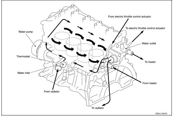
Engine Cooling System
M/T models
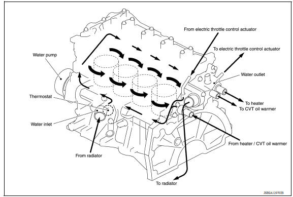
CVT and A/T models
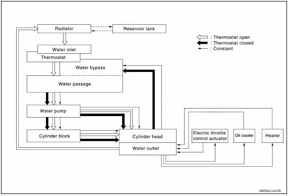
Engine Cooling System Schematic
M/T models
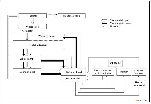
CVT and A/T models
OVERHEATING CAUSE ANALYSIS
Troubleshooting Chart
|
Symptom |
Check items | |||
| Cooling system parts malfunction | Poor heat transfer | Water pump malfunction | Worn or loose drive belt | |
| Thermostat stuck closed | Thermostat | |||
| Damaged fins | Dust contamination or paper clogging | |||
| Physical damage | ||||
| Clogged radiator cooling tube | Excess foreign material (rust, dirt, sand, etc.) | |||
| Reduced air flow | Cooling fan does not operate | Fan assembly | ||
| High resistance to fan rotation | ||||
| Damaged fan blades | ||||
| Damaged radiator shroud | Radiator shroud | |||
| Improper engine coolant mixture ratio | Engine coolant viscosity | |||
| Poor engine coolant quality | Periodic maintenance | |||
| Insufficient engine coolant
|
Engine coolant leakage | Cooling hose | Loose clamp | |
| Cracked hose | ||||
| Water pump | Poor sealing | |||
| Radiator cap | Loose | |||
| Poor sealing | ||||
| Radiator | Oring for damage, deterioration or improper fitting | |||
| Cracked radiator tank | ||||
| Cracked radiator core | ||||
| Reservoir tank | Cracked reservoir tank | |||
| Overflowing reservoir tank | Exhaust gas leaking into cooling system | Cylinder head deterioration | ||
| Cylinder head gasket deterioration | ||||
| Except cooling system parts malfunction | Overload on engine | Abusive driving | High engine rpm under no load | |
| Driving in low gear for extended time | ||||
| Driving at extremely high speed | ||||
| Power train system malfunction | ||||
| Installed improper size wheels and tires | ||||
| Dragging brakes | ||||
| Improper ignition timing | ||||
| Blocked or restricted air flow | Blocked bumper | Installed front bumper fascia cover | ||
| Blocked radiator grille | Mud contamination or paper clogging | |||
| Blocked radiator | Blocked air flow | |||
| Blocked condenser | ||||
| Installed large fog lamp | ||||
 Precaution
Precaution for Supplemental Restraint System (SRS) "AIR BAG" and "SEAT BELT PRETENSIONER" The Supplemental Restraint System such as "AIR BAG" and "SEAT BELT PRETENSIONER", used ...

Other materials:
Rear drum brake
Exploded View
1. Shoe hold pin 2. Back plate 3. Plug
4. Brake shoe 5. Spring 6. Upper spring
7. Adjuster 8. Return spring 9. Brake drum
10. Boot 11. Piston 12. Piston cup
13. Spring 14. Wheel cylinder 15. Bleeder valve
16. Cap
1: Apply rubber grease.
2: Apply PBC (Poly Butyl Cuprysil) ...
C1110, C1153, C1170 ABS Actuator and
electric unit (control unit)
DTC Logic
DTC DETECTION LOGIC
DTC CONFIRMATION PROCEDURE
1.CHECK SELF-DIAGNOSIS RESULTS
Check the self-diagnosis results. &nbs ...
Categories
- Manuals Home
- Nissan Versa Owners Manual
- Nissan Versa Service Manual
- Video Guides
- Questions & Answers
- External Resources
- Latest Updates
- Most Popular
- Sitemap
- Search the site
- Privacy Policy
- Contact Us

0.0047