
Nissan Versa (N17): Diagnosis and repair workflow
Workflow
OVERALL SEQUENCE
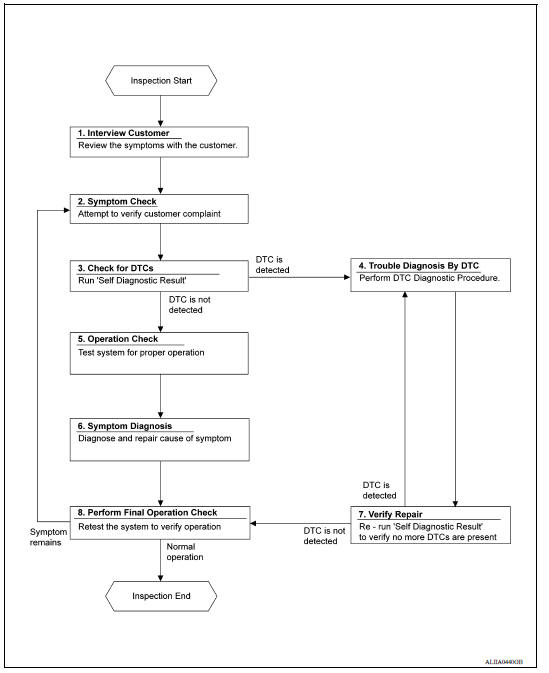
DETAILED FLOW
1.INTERVIEW CUSTOMER
Interview the customer to obtain as much information as possible about the conditions and environment under which the malfunction occurred.
>> GO TO 2.
2.SYMPTOM CHECK
Verify symptoms.
>> GO TO 3.
3.CHECK FOR DTCS
With CONSULT
- Turn ignition switch ON.
- Select "Self Diagnostic Result" mode of "BCM" using CONSULT.
- Check DTC.
Is any DTC detected?
YES >> GO TO 4.
NO >> GO TO 5.
4.PERFORM DTC DIAGNOSTIC PROCEDURE
Perform the diagnostic procedure for the detected DTC. Refer to BCS "DTC Inspection Priority Chart" or BCS "DTC Inspection Priority Chart".
>> GO TO 7.
5.OPERATION CHECK
Perform the operation check. Refer to HAC "Work Procedure".
>> GO TO 6.
6.SYMPTOM DIAGNOSIS
Check the symptom diagnosis table. Refer to HAC "Symptom Table".
>> GO TO 8.
7.VERIFY REPAIR.
With CONSULT
- Turn ignition switch ON.
- Select "Self Diagnostic Result" mode of "BCM" using CONSULT.
- Check DTC.
Is any DTC detected?
YES >> GO TO 4.
NO >> GO TO 8.
8.PERFORM FINAL OPERATION CHECK
Perform the operation check. Refer to HAC "Work Procedure".
Does it operate normally?
YES >> Inspection End.
NO >> GO TO 2.
 Manual air conditioning system
MANUAL AIR CONDITIONING SYSTEM : System Diagram MANUAL AIR CONDITIONING SYSTEM : System Description The manual air conditioning system is controlled by a sequence of functions from ...
Operation inspection
Work Procedure The purpose of the operation inspection is to check that the individual system operates normally. Check condition : Engine running at normal operating temperature. 1.CHECK F ...
Other materials:
P2760 Torque converter
Description
This DTC is detected when the torque converter clutch solenoid valve is
electrically normal but the torque converter
clutch does not engage. This is not due to an electrical malfunction (circuit
open or shorted), but is
instead due to a mechanical malfunction (sticking of the con ...
Hood lock secondary control
HOOD LOCK SECONDARY CONTROL : Removal
and Installation
REMOVAL
Remove radiator upper seal clips and then remove upper clip from
radiator side seal (RH). Refer to DLK "Exploded View".
Remove hood lock secondary control nuts and hood lock secondary control.
INSTALLATION
Instal ...
Categories
- Manuals Home
- Nissan Versa Owners Manual
- Nissan Versa Service Manual
- Video Guides
- Questions & Answers
- External Resources
- Latest Updates
- Most Popular
- Sitemap
- Search the site
- Privacy Policy
- Contact Us

0.0158