Nissan Versa (N17): Diagnosis and repair workflow
Work Flow
OVERALL SEQUENCE
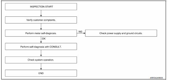
DETAILED FLOW
1.CONFIRM SYMPTOM
Confirm symptom or customer complaint.
>> GO TO 2
2.SELF-DIAGNOSIS OF COMBINATION METER
Perform self-diagnosis of combination meter. Refer to MWI "Diagnosis Description".
Is the inspection result normal?
YES >> GO TO 3
NO >> If self-diagnosis will not start, check power supply and ground circuit of combination meter. Refer to MWI "COMBINATION METER : Diagnosis Procedure". If power supply and ground circuits are OK, replace combination meter. Refer to MWI "Removal and Installation".
3.CHECK COMBINATION METER WITH CONSULT
Select "METER/M&A" on CONSULT and perform self-diagnosis of combination meter. Refer to MWI "CONSULT Function".
Is the inspection result normal?
YES >> Check symptom. GO TO 4.
NO >> Refer to MWI "DTC Index".
4.CHECK SYSTEM OPERATION
Check the combination meter to verify that the repair has been completed successfully.
Is the inspection result normal?
YES >> Inspection End.
NO >> GO TO 1
DTC/CIRCUIT DIAGNOSIS
 Diagnosis system (combination
meter)
Diagnosis system (combination
meter)U1000 CAN Comm circuit
DTC Logic DTC DETECTION LOGIC Diagn ...
Other materials:
Fuel injector and fuel tube
Exploded View
1. Stud bolt 2. Oring (green) 3. Fuel injector (front) 4. Clip 5. Fuel
injector (rear) 6. Oring (black) 7. Fuel tube protector 8. Fuel tube 9. Clamp
10. Quick connector cap (engine side) 11. Fuel feed hose 12. Quick connector cap
(floor pipingside) 13. Fuel connector protect ...
P0712 Transmission fluid temperature
sensor A
DTC Logic
DTC DETECTION LOGIC
DTC
Trouble diagnosis name
DTC detection condition
Possible causes
P0712
Transmission Fluid Temperature
Sensor "A" Circuit Low
Under the following diagnosis
conditions, the A/T fluid temperature
identified by TCM is
180C (3 ...
Categories
- Manuals Home
- Nissan Versa Owners Manual
- Nissan Versa Service Manual
- Video Guides
- Questions & Answers
- External Resources
- Latest Updates
- Most Popular
- Sitemap
- Search the site
- Privacy Policy
- Contact Us

0.0057