Nissan Versa (N17): Overdrive control switch
Component Function Check
1.CHECK OD OFF INDICATOR LAMP FUNCTION
Check OD OFF indicator lamp turns ON for approx. 2 seconds when ignition switch turns ON.
Is the inspection results normal?
YES >> GO TO 2.
NO >> Go to TM "Diagnosis Procedure".
2.CHECK OVERDRIVE CONTROL SWITCH FUNCTION
- Shift the selector lever to "D" position.
- Check that OD OFF indicator lamp turns ON/OFF when overdrive control switch is operated.
Is the inspection results normal?
YES >> INSPECTION END
NO >> Go to TM "Diagnosis Procedure".
Diagnosis Procedure
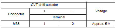
1.CHECK OVERDRIVE CONTROL SWITCH CIRCUIT
- Turn ignition switch OFF.
- Disconnect CVT shift selector connector.
- Turn ignition switch ON.
- Check voltage between CVT shift selector harness connector terminals.
Is the inspection result normal?
YES >> GO TO 2.
NO >> GO TO 4.
2.CHECK OVERDRIVE CONTROL SWITCH
Check overdrive control switch. Refer to TM "Component Inspection (Overdrive Control Switch)".
Is the inspection result normal?
YES >> GO TO 3.
NO >> Repair or replace malfunctioning parts.
3.CHECK GROUND CIRCUIT
Check continuity between CVT shift selector harness connector terminal and
ground. 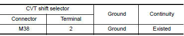
Is the inspection result normal?
YES >> GO TO 4.
NO >> Repair or replace malfunctioning parts.
4.CHECK CIRCUIT BETWEEN COMBINATION METER AND CVT SHIFT SELECTOR (PART 1)
- Turn ignition switch OFF.
- Disconnect combination meter connector.
- Check continuity between combination meter harness connector terminal
and CVT shift selector harness
connector terminal.
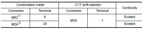
*1: TYPE A (Refer to MWI "Information".) *2: TYPE B (Refer to MWI "Information".)
Is the inspection result normal?
YES >> GO TO 5.
NO >> Repair or replace malfunctioning parts.
5.CHECK CIRCUIT BETWEEN COMBINATION METER AND CVT SHIFT SELECTOR (PART 2)
Check continuity between combination meter harness connector terminal and
ground. 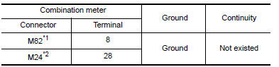
*1: TYPE A (Refer to MWI-55, "Information".) *2: TYPE B (Refer to MWI-5, "Information".)
Is the inspection result normal?
YES >> GO TO 6.
NO >> Repair or replace malfunctioning parts.
6.CHECK COMBINATION METER INPUT SIGNAL
- Connect all of disconnected connectors.
- Turn ignition switch ON.
- Select "Data Monitor" in "METER/M&A".
- Select "O/D OFF SW".
Check that "O/D OFF SW" turns ON/OFF when overdrive control switch is operated. Refer to MWI "Reference Value".
Is the inspection result normal?
YES >> Check intermittent incident. Refer to GI "Intermittent Incident".
NO >> Replace combination meter. Refer to MWI "Removal and Installation".
Component Inspection (Overdrive Control Switch)
1.CHECK OVERDRIVE CONTROL SWITCH
Check continuity between wires of selector lever knob (1)
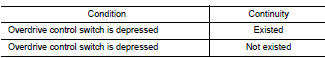
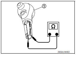
Is the inspection result normal?
YES >> INSPECTION END
NO >> Replace selector lever knob. Refer to TM"Removal and Installation".
 Main power supply and ground circuit
Diagnosis Procedure 1.CHECK TCM POWER CIRCUIT (PART 1) Turn ignition switch OFF. Disconnect TCM connector. Check voltage between TCM harness connector terminals and ground. & ...
OD OFF indicator lamp
Component Function Check 1.CHECK OD OFF INDICATOR LAMP FUNCTION Check OD OFF indicator lamp turns ON for approx. 2 seconds when ignition switch turns ON. Is the inspection results normal? YES &g ...
Other materials:
Installing front license plate
Use the following steps to mount the front license
plate:
Before mounting the license plate, confirm that
the following parts are enclosed in the plastic
bag:
License plate bracket
License plate bracket screws x 2
Screw grommets x 2
1. Hold the license plate bracket 1 and make
a ...
Shift lock system
Component Function Check
1.CHECK SHIFT LOCK OPERATION (BRAKE PEDAL RELEASED)
Ignition switch ON.
Attempt to shift selector lever to any position other than "P" position
with brake pedal released.
Can the selector lever be shifted?
YES >> Go to TM "Diagnosis Procedure".
...
Categories
- Manuals Home
- Nissan Versa Owners Manual
- Nissan Versa Service Manual
- Video Guides
- Questions & Answers
- External Resources
- Latest Updates
- Most Popular
- Sitemap
- Search the site
- Privacy Policy
- Contact Us

0.0059