Nissan Versa (N17): Main power supply and ground circuit
Diagnosis Procedure
1.CHECK TCM POWER CIRCUIT (PART 1)
- Turn ignition switch OFF.
- Disconnect TCM connector.
- Check voltage between TCM harness connector terminals and ground.
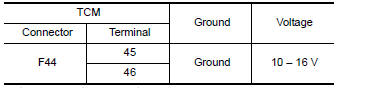
Is the inspection result normal?
YES >> GO TO 2.
NO >> GO TO 4.
2.CHECK TCM POWER CIRCUIT (PART 2)
Check voltage between TCM harness connector terminals and ground. 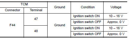
Is the inspection result normal?
YES >> GO TO 3.
NO >> GO TO 5.
3.CHECK TCM GROUND CIRCUIT
Check continuity between TCM harness connector terminals and ground. 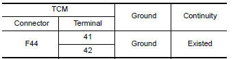
Is the inspection result normal?
YES >> Check intermittent incident. Refer to GI "Intermittent Incident".
NO >> Repair or replace malfunctioning parts.
4.DETECT MALFUNCTION ITEMS (PART 1)
Check the following items:
- Open or short circuit of harness between battery positive terminal and TCM connectors terminals 45 and 46.
- 10A fuse (No.33, fuse and fusible link block). Refer to PG "Terminal Arrangement".
Is the inspection result normal?
YES >> Check intermittent incident. Refer to GI "Intermittent Incident".
NO >> Repair or replace malfunctioning parts.
5.CHECK CIRCUIT BETWEEN IPDM E/R AND TCM (PART 1)
- Turn ignition switch OFF.
- Disconnect IPDM E/R connector.
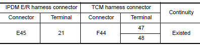
- Check continuity between IPDM E/R harness connector terminal and TCM harness connector terminals.
Is the check result normal?
YES >> GO TO 6.
NO >> Repair or replace malfunctioning parts.
6.CHECK CIRCUIT BETWEEN IPDM E/R AND TCM (PART 2)
Check continuity between IPDM E/R harness connector terminal and ground. 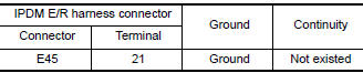
Is the check result normal?
YES >> GO TO 7.
NO >> Repair or replace malfunctioning parts.
7.DETECT MALFUNCTIONING ITEMS (PART 2)
Check the following items:
- Harness open circuit or short circuit between ignition switch and IPDM E/R. Refer to PG "Wiring Diagram - Ignition Power Supply -".
- 10A fuse (No.49, IPDM E/R). Refer to PG "IPDM E/R Terminal Arrangement".
- IPDM E/R
Is the check result normal?
YES >> Check intermittent incident. Refer to GI "Intermittent Incident".
NO >> Repair or replace malfunctioning parts.
 P285A Clutch B pressure
DTC Logic DTC DETECTION LOGIC DTC Trouble diagnosis name DTC detection condition Possible causes P285A Clutch B pressure disengagement performance The detection con ...

Other materials:
Instrument panel
1. Headlight/turn signal switch/fog light
switch (if so equipped)
2. Driver's supplemental air bag (P. 1-39)
Horn
3. Meters and gauges. Warning and indicator lights
4. Wiper and washer switch
5. Vents
6. Rear window defroster switch
7. Front passenger air bag status light
8. Hazard warn ...
Car phone or CB radio
When installing a CB, ham radio or car phone in
your vehicle, be sure to observe the following
precautions; otherwise, the new equipment may
adversely affect the engine control system and
other electronic parts.
WARNING
A cellular phone should not be used for
any purpose while driving so ...
Categories
- Manuals Home
- Nissan Versa Owners Manual
- Nissan Versa Service Manual
- Video Guides
- Questions & Answers
- External Resources
- Latest Updates
- Most Popular
- Sitemap
- Search the site
- Privacy Policy
- Contact Us

0.0047