Nissan Versa (N17): Overdrive control switch
Component Function Check
1.CHECK OD OFF INDICATOR LAMP FUNCTION
Check OD OFF indicator lamp turns ON for approx. 2 seconds when ignition switch turns ON.
Is the inspection results normal?
YES >> GO TO 2.
NO >> Go to TM "Diagnosis Procedure".
2.CHECK OVERDRIVE CONTROL SWITCH FUNCTION
- Shift the selector lever to "D" position.
- Check that OD OFF indicator lamp turns ON/OFF when overdrive control switch is operated.
Is the inspection results normal?
YES >> INSPECTION END
NO >> Go to TM "Diagnosis Procedure".
Diagnosis Procedure
1.CHECK OVERDRIVE CONTROL SWITCH CIRCUIT
- Turn ignition switch OFF.
- Disconnect CVT shift selector connector.
- Turn ignition switch ON.
- Check voltage between CVT shift selector harness connector terminals.
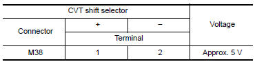
Is the inspection result normal?
YES >> GO TO 2.
NO >> GO TO 4.
2.CHECK OVERDRIVE CONTROL SWITCH
Check overdrive control switch. Refer to TM "Component Inspection (Overdrive Control Switch)".
Is the inspection result normal?
YES >> GO TO 3.
NO >> Repair or replace malfunctioning parts.
3.CHECK GROUND CIRCUIT
Check continuity between CVT shift selector harness connector terminal and
ground. 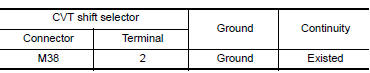
Is the inspection result normal?
YES >> GO TO 4.
NO >> Repair or replace malfunctioning parts.
4.CHECK CIRCUIT BETWEEN COMBINATION METER AND CVT SHIFT SELECTOR (PART 1)
- Turn ignition switch OFF.
- Disconnect combination meter connector.
- Check continuity between combination meter harness connector terminal
and CVT shift selector harness
connector terminal.
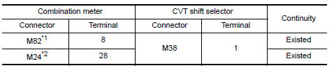
*1: TYPE A (Refer to MWI "Information".) *2: TYPE B (Refer to MWI "Information".)
Is the inspection result normal?
YES >> GO TO 5.
NO >> Repair or replace malfunctioning parts.
5.CHECK CIRCUIT BETWEEN COMBINATION METER AND CVT SHIFT SELECTOR (PART 2)
Check continuity between combination meter harness connector terminal and
ground. 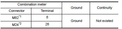
*1: TYPE A (Refer to MWI-55, "Information".) *2: TYPE B (Refer to MWI-5, "Information".)
Is the inspection result normal?
YES >> GO TO 6.
NO >> Repair or replace malfunctioning parts.
6.CHECK COMBINATION METER INPUT SIGNAL
- Connect all of disconnected connectors.
- Turn ignition switch ON.
- Select "Data Monitor" in "METER/M&A".
- Select "O/D OFF SW".
Check that "O/D OFF SW" turns ON/OFF when overdrive control switch is operated. Refer to MWI "Reference Value".
Is the inspection result normal?
YES >> Check intermittent incident. Refer to GI "Intermittent Incident".
NO >> Replace combination meter. Refer to MWI "Removal and Installation".
Component Inspection (Overdrive Control Switch)
1.CHECK OVERDRIVE CONTROL SWITCH
Check continuity between wires of selector lever knob (1)
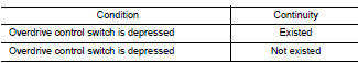
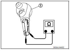
Is the inspection result normal?
YES >> INSPECTION END
NO >> Replace selector lever knob. Refer to TM"Removal and Installation".
 Main power supply and ground circuit
Diagnosis Procedure 1.CHECK TCM POWER CIRCUIT (PART 1) Turn ignition switch OFF. Disconnect TCM connector. Check voltage between TCM harness connector terminals and ground. & ...
OD OFF indicator lamp
Component Function Check 1.CHECK OD OFF INDICATOR LAMP FUNCTION Check OD OFF indicator lamp turns ON for approx. 2 seconds when ignition switch turns ON. Is the inspection results normal? YES &g ...
Other materials:
Power outlets
Instrument panel
Console (if so equipped)
The power outlets are for powering electrical
accessories such as cellular telephones. The
outlets are rated at 12 volt, 120W (10A) maximum.
CAUTION
The outlet and plug may be hot during
or immediately after use.
Only certain power outlets ...
Noise, vibration and harshness (NVH) troubleshooting
NVH troubleshooting Chart
Locate the area where noise occurs.
Confirm the type of noise.
Specify the operating condition of engine.
Check specified noise source
If necessary, repair or replace these parts.
Location
of noise
Type of
noise
Operating condition of
...
Categories
- Manuals Home
- Nissan Versa Owners Manual
- Nissan Versa Service Manual
- Video Guides
- Questions & Answers
- External Resources
- Latest Updates
- Most Popular
- Sitemap
- Search the site
- Privacy Policy
- Contact Us

0.0068