Nissan Versa (N17): Tire pressure monitoring system
TIRE PRESSURE MONITORING SYSTEM : System Diagram
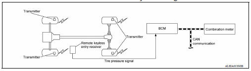
TIRE PRESSURE MONITORING SYSTEM : System Description
- The BCM has pressure judgment and trouble diagnosis functions. When the BCM detects low inflation pressure or another unusual symptom, the low tire pressure warning lamp in the combination meter is illuminated.
- If the tire pressure is less than the specified value, the low tire pressure warning lamp illuminates.
- The TPMS (Tire Pressure Monitoring System) is activated when vehicle speed is 40 km/h (25 MPH) or more.
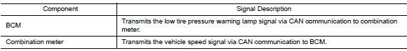
INPUT/OUTPUT SIGNAL
LOW TIRE PRESSURE WARNING LAMP CONTROL CONDITION
The BCM uses CAN communication to illuminate the low tire pressure warning
lamp in the combination meter.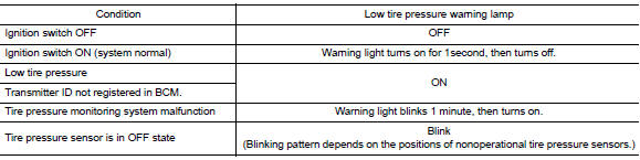
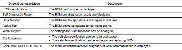
DIAGNOSIS SYSTEM (BCM) (WITH INTELLIGENT KEY SYSTEM)
COMMON ITEM
COMMON ITEM : CONSULT Function (BCM - COMMON ITEM)
APPLICATION ITEM
CONSULT performs the following functions via CAN communication with BCM.
SYSTEM APPLICATION
BCM can perform the following functions.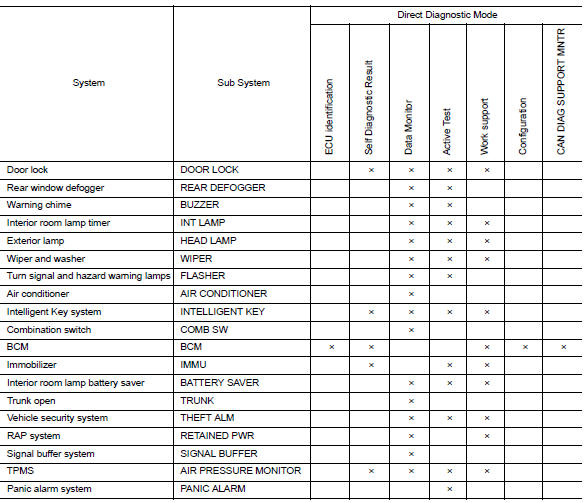
 Component parts
Component Parts Location 1 BCM (view with instrument panel removed) 2 Remote keyless entry receiver (view with instrument panel removed) 3 Transmitter 4 Combination meter (with type A) 5 Com ...
Air pressure monitor
AIR PRESSURE MONITOR : CONSULT Function (BCM - AIR PRESSURE MONITOR) NOTE: The Signal Tech II Tool (J-50190) can be used to perform the following functions. Refer to the Signal Tech II User Gui ...
Other materials:
Push-button ignition switch (if so equipped)
WARNING
Do not operate the push-button ignition
switch while driving the vehicle except in
an emergency. (The engine will stop when
the ignition switch is pushed 3 consecutive
times in quick succession or the ignition
switch is pushed and held for more
than 2 seconds.) If the engine stops ...
Fuel injector and fuel tube
Exploded View
1. Stud bolt 2. Oring (green) 3. Fuel injector (front) 4. Clip 5. Fuel
injector (rear) 6. Oring (black) 7. Fuel tube protector 8. Fuel tube 9. Clamp
10. Quick connector cap (engine side) 11. Fuel feed hose 12. Quick connector cap
(floor pipingside) 13. Fuel connector protect ...
Categories
- Manuals Home
- Nissan Versa Owners Manual
- Nissan Versa Service Manual
- Video Guides
- Questions & Answers
- External Resources
- Latest Updates
- Most Popular
- Sitemap
- Search the site
- Privacy Policy
- Contact Us

0.0136