Nissan Versa (N17): B1350 Front door satellite sensors
Description
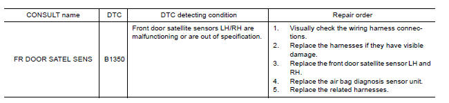
DTC B1350 FRONT DOOR SATELLITE SENSORS LH/RH
The front door satellite sensors LH/RH are wired to the air bag diagnosis sensor unit. The air bag diagnosis sensor unit will monitor the front door satellite sensors LH/RH for internal failures and check if the sensors are within specification.
PART LOCATION
Refer to SRC "Component Parts Location".
DTC Logic
DTC DETECTION LOGIC
With CONSULT
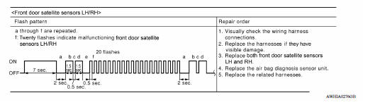
Without CONSULT
DTC CONFIRMATION PROCEDURE (With CONSULT)
1.CHECK SELF-DIAG RESULT
- Turn ignition switch ON.
- Check for DTC using CONSULT.
Is the DTC detected?
YES (Current DTC)>>Refer to SRC "Diagnosis Procedure".
YES (Past DTC)>>GO TO 2.
NO >> Inspection End.
2.ERASE SELF-DIAG RESULT
Erase the DTC using CONSULT.
Can the DTC be erased?
YES >> Inspection End.
NO >> Refer to SRC "Diagnosis Procedure".
DTC CONFIRMATION PROCEDURE (Without CONSULT)
1.CHECK SELF-DIAG RESULT
- Turn ignition switch ON.
- Check the air bag warning lamp status. Refer to SRC "Trouble Diagnosis without CONSULT".
NOTE: SRS will not enter diagnosis mode if no malfunction is detected in user mode.
Is the DTC detected?
YES >> Refer to SRC "Diagnosis Procedure".
NO >> Inspection End.
Diagnosis Procedure
1.HARNESS CONNECTOR
Visually inspect all applicable harness connectors for the following:
- Visible damage to connector or terminal
- Loose terminal
- Poor connection
NOTE: All harness connectors should be inspected from the air bag diagnosis unit to the end component (including any in-line connectors).
Is the inspection result normal?
YES >> GO TO 2.
NO >> Perform one of the following repairs:
- Visible damage: Replace the harness.
- Loose terminal: Secure the terminal.
- Poor connection: Secure the connection.
2.CONFIRM DTC
- Reconnect all harness connectors.
- Turn ignition switch ON.
- Check for DTC using CONSULT.
Is DTC still current?
YES >> GO TO 3
NO >> Refer to GI "Intermittent Incident".
3.WIRING HARNESS
Check the wiring harness for visible damage NOTE.
NOTE: The entire wiring harness should be inspected from the air bag diagnosis sensor unit to the end component (including any in-line connectors).
Is the inspection result normal?
YES >> GO TO 4.
NO >> Replace the harness.
4.CONFIRM DTC
- Reconnect all harness connectors.
- Turn ignition switch ON.
- Check for DTC using CONSULT.
Is DTC still current?
YES >> GO TO 5.
NO >> Refer to GI "Intermittent Incident".
5.AIR BAG DIAGNOSIS SENSOR UNIT
- Replace the air bag diagnosis sensor unit. Refer to SR "Removal and Installation".
- Turn ignition switch ON.
- Check for DTC using CONSULT.
Is DTC still current?
YES >> GO TO 6.
NO >> Clear DTC. Inspection End.
6.FRONT DOOR SATELLITE SENSOR
Replace the front door satellite sensor LH and RH. Refer to SR "Removal and Installation".
>> GO TO 7
7.RELATED HARNESS
Replace the related harness.
>> END
 B1336 - B1342 Front door satellite
sensor RH
B1336 - B1342 Front door satellite
sensor RH
Description DTC B1336 - B1342 FRONT DOOR SATELLITE SENSOR RH The front door satellite sensor RH is wired to the air bag diagnosis sensor unit. The air bag diagnosis sensor unit will monitor the f ...
B1XXX Air bag diagnosis sensor unit
Description DTC B1XXX AIR BAG DIAGNOSIS SENSOR UNIT The air bag diagnosis sensor unit will run self diagnostics when the ignition switch is turned ON. It has the potential to set many diagnostic ...
Other materials:
Transaxle
Transaxle : cross-sectional view
1. Converter housing 2. Oil pump 3. Low clutch
4. Rear planetary gear 5. Low & reverse brake 6. Front planetary gear
7. Low one-way clutch 8. High clutch 9. Reverse clutch
10. 2-4 brake band (Brake band) 11. Band servo piston 12. Side cover
13. Output ...
P073E Unable to engage r range
Description
This malfunction is detected when the A/T does not shift into reverse
position as instructed by TCM. This is not
only caused by electrical malfunction (circuits open or shorted) but by
mechanical malfunction such as control
valve sticking, improper solenoid valve operation, etc
D ...
Categories
- Manuals Home
- Nissan Versa Owners Manual
- Nissan Versa Service Manual
- Video Guides
- Questions & Answers
- External Resources
- Latest Updates
- Most Popular
- Sitemap
- Search the site
- Privacy Policy
- Contact Us

0.0051