Nissan Versa (N17): B2622 Inside antenna
DTC Logic
DTC DETECTION LOGIC 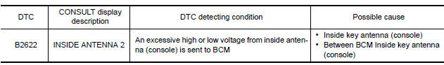
DTC CONFIRMATION PROCEDURE
1.PERFORM DTC CONFIRMATION PROCEDURE
- Select INTELLIGENT KEY of BCM using CONSULT.
- Select INSIDE ANT DIAGNOSIS in WORK SUPPORT mode.
- Perform inside key antenna (INSIDE ANT DIAGNOSIS) on WORK SUPPORT of INTELLIGENT KEY.
- Check BCM for DTC.
Is inside key antenna DTC detected?
YES >> Refer to DLK "Diagnosis Procedure".
NO >> Inside key antenna (console) is OK.
Diagnosis Procedure
Regarding Wiring Diagram information, refer to DLK "INTELLIGENT KEY SYSTEM : Wiring Diagram".
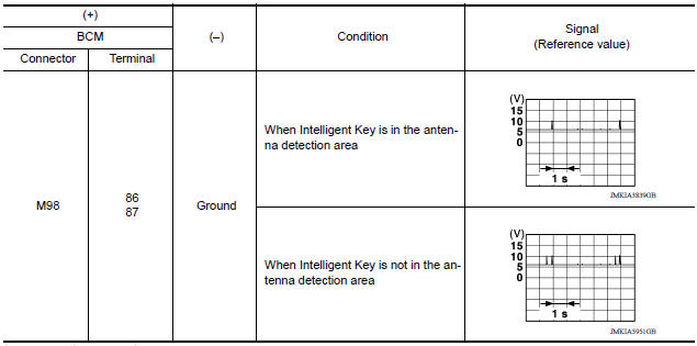
1.CHECK INSIDE KEY ANTENNA INPUT SIGNAL 1
- Turn ignition switch ON.
- Check signal between BCM harness connector and ground using
oscilloscope.
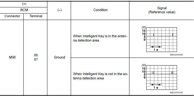
Is the inspection result normal?
YES >> Replace BCM. Refer to BCS "Removal and Installation".
NO >> GO TO 2.
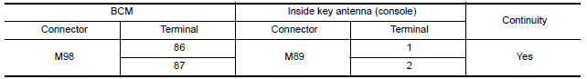
2.CHECK INSIDE KEY ANTENNA CIRCUIT
- Turn ignition switch OFF.
- Disconnect BCM connector and inside key antenna (console) connector.
- Check continuity between BCM harness connector and inside key antenna
(console) harness connector
- Check continuity between BCM harness connector and ground.
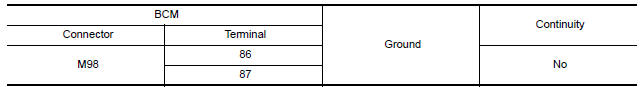
Is the inspection result normal?
YES >> GO TO 3.
NO >> Repair or replace harness.
3.CHECK INSIDE KEY ANTENNA INPUT SIGNAL 2
- Replace inside key antenna (console). (New antenna or other antenna)
- Connect BCM connector and inside key antenna (console) connector.
- Turn ignition switch ON.
- Check signal between BCM harness connector and ground using
oscilloscope.
Is the inspection result normal?
YES >> Replace inside key antenna (console).
NO >> Replace BCM. Refer to BCS "Removal and Installation".
 B2621 Inside antenna
Other materials:
Uniform tire quality grading
DOT (Department of Transportation) Quality
Grades: All passenger car tires must conform to
federal safety requirements in addition to these
grades.
Quality grades can be found where applicable on
the tire sidewall between tread shoulder and
maximum section width. For example:
Treadwear 200 ...
EVAP canister
Exploded View
1. EVAP control system pressure sensor 2. O-ring 3. EVAP canister
4. Hose clamp 5. EVAP canister purge hose 6. EVAP vent line
7. O-ring 8. EVAP canister vent control valve 9. EVAP canister vent control
valve
hose
A. Mount to vehicle bracket
Removal and Installation
NOTE: ...
Categories
- Manuals Home
- Nissan Versa Owners Manual
- Nissan Versa Service Manual
- Video Guides
- Questions & Answers
- External Resources
- Latest Updates
- Most Popular
- Sitemap
- Search the site
- Privacy Policy
- Contact Us

0.0066