Nissan Versa (N17): EVAP canister
Exploded View
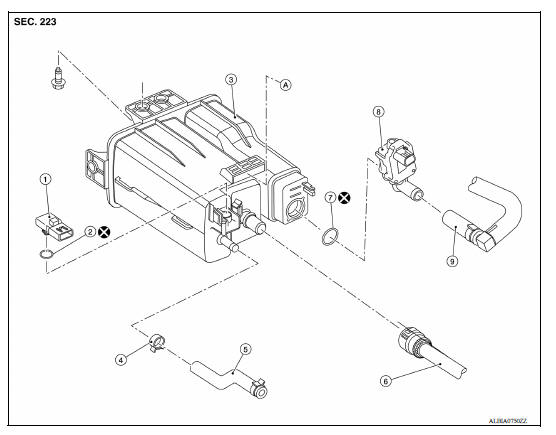
1. EVAP control system pressure sensor 2. O-ring 3. EVAP canister 4. Hose clamp 5. EVAP canister purge hose 6. EVAP vent line 7. O-ring 8. EVAP canister vent control valve 9. EVAP canister vent control valve hose A. Mount to vehicle bracket
Removal and Installation
NOTE: The EVAP canister vent control valve and EVAP canister system pressure sensor can be removed without removing the EVAP canister.
REMOVAL
- Remove the EVAP canister protector cover.
- Disconnect the harness connectors from the EVAP control system pressure sensor and the EVAP canister vent control valve.
- Disconnect the EVAP canister purge hose, the EVAP vent line, and the EVAP canister vent control valve hose.
- Remove the EVAP canister bolt.
- Remove the EVAP canister from the vehicle.
INSTALLATION
Installation is in the reverse order of removal.
CAUTION: Do not reuse O-rings.
Inspection
Check EVAP canister as follows:
- Block port (B).
- Blow air into port (A) and check that it flows freely out of port (C).
- Release blocked port (B).
- Apply vacuum pressure to port (B) and check that vacuum pressure exists at the ports (A) and (C).
- Block port (A) and (B).
- Apply pressure to port (C) and check that there is no leakage.
 Fuel tank
Exploded View 1. Fuel tank 2. Fuel tank mounting band (RH) 3. Fuel tank mounting band (LH) 4. Clamp 5. Fuel filler hose 6. Fuel filler tube 7. Grommet 8. Fuel filler cap 9. Clamp 10. Vent hose ...
EVAP canister filter
Exploded View 1. EVAP canister vent control valve hose 2. Canister drain hose 3. EVAP canister filter Front Removal and Installation REMOVAL Remove the EVAP canister protector cover. ...
Other materials:
U0155 Lost communication (IPC)
Description
CAN (Controller Area Network) is a serial communication line for real-time
application. It is an on-vehicle multiplex
communication line with high data communication speed and excellent malfunction
detection ability.
Many electronic control units are equipped onto a vehicle, and ...
Parking brake control
Exploded View
1. Parking brake lever assembly 2. Adjusting nut 3. Parking brake switch
4. Front cable 5. Rear cable (LH) 6. Rear cable (RH)
Removal and Installation
REMOVAL
Remove rear wheel and tire assemblies using power tool. Refer to WT
"Adjustment".
Remove the center ...
Categories
- Manuals Home
- Nissan Versa Owners Manual
- Nissan Versa Service Manual
- Video Guides
- Questions & Answers
- External Resources
- Latest Updates
- Most Popular
- Sitemap
- Search the site
- Privacy Policy
- Contact Us

0.005