Nissan Versa (N17): B2626 Outside antenna
DTC Logic
DTC DETECTION LOGIC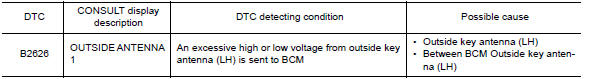
DTC CONFIRMATION PROCEDURE
1.PERFORM DTC CONFIRMATION PROCEDURE
- Turn ignition switch ON.
- Check "Self Diagnostic Result" mode of "BCM" using CONSULT.
Is DTC detected?
YES >> Refer to DLK "Diagnosis Procedure".
NO >> Outside key antenna (LH) is OK.
Diagnosis Procedure
Regarding Wiring Diagram information, refer to DLK "INTELLIGENT KEY SYSTEM : Wiring Diagram".
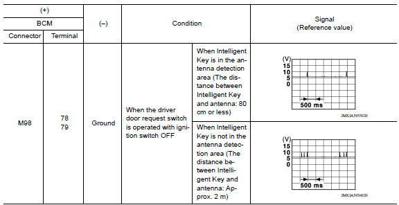
1.CHECK OUTSIDE KEY ANTENNA INPUT SIGNAL 1
- Turn ignition switch ON.
- Check signal between BCM harness connector and ground using
oscilloscope.
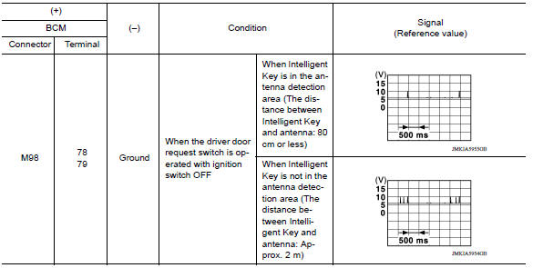
Is the inspection result normal?
YES >> Replace BCM. Refer to BCS "Removal and Installation".
NO >> GO TO 2.
2.CHECK OUTSIDE KEY ANTENNA CIRCUIT
- Turn ignition switch OFF.
- Disconnect BCM connector and outside key antenna (LH) connector.
- Check continuity between BCM harness connector and outside key antenna (LH)
harness connector.
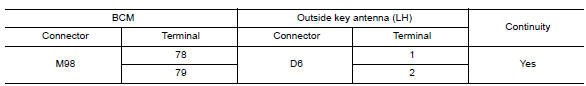
- Check continuity between BCM harness connector and ground.
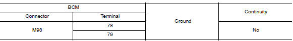
Is the inspection result normal?
YES >> GO TO 3.
NO >> Repair or replace harness.
3.CHECK OUTSIDE KEY ANTENNA INPUT SIGNAL 2
- Replace outside key antenna (LH). (New antenna or other antenna)
- Connect BCM connector and outside key antenna (LH) connector.
- Turn ignition switch ON.
- Check signal between BCM harness connector and ground using
oscilloscope.
Is the inspection result normal?
YES >> Replace outside key antenna (LH).
NO >> Replace BCM. Refer to BCS "Removal and Installation".
 B2623 Inside antenna
Other materials:
Fuel filler cap warning system
FUEL FILLER CAP WARNING SYSTEM : System Diagram
FUEL FILLER CAP WARNING SYSTEM : System Description
INPUT/OUTPUT SIGNAL CHART
Input
Unit/Sensor
Input signal to ECM
ECM function
EVAP control system pressure sensor
Pressure in purge line
Fuel filler cap warning cont ...
Precautions
Precaution for Supplemental Restraint System
(SRS) "AIR BAG" and "SEAT BELT PRE-TENSIONER"
The Supplemental Restraint System such as "AIR BAG" and "SEAT BELT PRE-TENSIONER",
used along
with a front seat belt, helps to reduce the risk or severity of injury to the
driver and ...
Categories
- Manuals Home
- Nissan Versa Owners Manual
- Nissan Versa Service Manual
- Video Guides
- Questions & Answers
- External Resources
- Latest Updates
- Most Popular
- Sitemap
- Search the site
- Privacy Policy
- Contact Us

0.0053