Nissan Versa (N17): B2190, P1614 NATS antenna AMP
Description
Performs ID verification through BCM and NATS antenna amplifier when ignition key is inserted and ignition switch turned ON.
Prohibits the start of engine when an unregistered ID of ignition key is used.
DTC Logic
DTC DETECTION LOGIC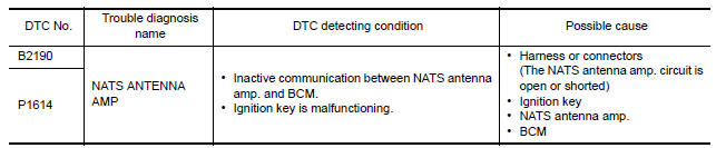
DTC CONFIRMATION PROCEDURE
1.PERFORM DTC CONFIRMATION PROCEDURE
1. Insert ignition key into the key cylinder.
2. Turn ignition switch ON.
3. Check "Self diagnostic result" with CONSULT.
Is DTC detected?
YES >> Refer to SEC "Diagnosis Procedure".
NO >> Inspection End.
Diagnosis Procedure
Regarding Wiring Diagram information, refer to SEC "Wiring Diagram".
1.CHECK NATS ANTENNA AMP. INSTALLATION
Check NATS antenna amp. installation. Refer to SEC "Removal and Installation".
Is the inspection result normal?
YES >> GO TO 2
NO >> Reinstall NATS antenna amp. correctly.
2.CHECK NVIS (NATS) IGNITION KEY ID CHIP
Start engine with another registered NATS ignition key.
Does the engine start?
YES >>
- Ignition key ID chip is malfunctioning.
- Replace the ignition key.
- Perform initialization with CONSULT.
- For initialization, refer to CONSULT Immobilizer mode and follow the on-screen instructions.
NO >> GO TO 3
3.CHECK POWER SUPPLY FOR NATS ANTENNA AMP.
1. Turn ignition switch ON.
2. Check voltage between NATS antenna amp. connector M21 terminal 1 and ground.
1 - Ground : Battery voltage
Is the inspection result normal?
YES >> GO TO 4
NO >> Repair or replace fuse or harness.
4.CHECK NATS ANTENNA AMP. GROUND LINE CIRCUIT
1. Turn ignition switch OFF.
2. Disconnect NATS antenna amp. connector.
3. Check continuity between NATS antenna amp. connector M21 terminal 3 and ground.
Is the inspection result normal?
YES >> GO TO 5
NO >> Repair or replace harness.
NOTE: If harness is OK, replace BCM BCS "Removal and Installation". Perform initialization with CONSULT. For initialization, refer to CONSULT Immobilizer mode and follow the on-screen instructions.
5.CHECK NATS ANTENNA AMP. SIGNAL LINE- 1
1. Connect NATS antenna amp. connector.
2. Turn ignition switch ON.
3. Check voltage between NATS antenna amp. connector M21 terminal 2 and
ground with analog tester.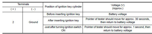
Is the inspection result normal?
YES >> GO TO 6
NO >> Repair or replace harness.
NOTE: If harness is OK, replace BCM BCS "Removal and Installation". Perform initialization with CONSULT. For initialization, refer to CONSULT Immobilizer mode and follow the on-screen instructions.
6.CHECK NATS ANTENNA AMP. SIGNAL LINE- 2
Check voltage between NATS antenna amp. connector M21 terminal 4 and ground
with analog tester. 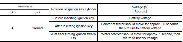
Is the inspection result normal?
YES >> NATS antenna amp. is malfunctioning. Replace NATS antenna amp. Refer to SEC "Removal and Installation".
NO >> Repair or replace harness.
NOTE: If harness is OK, replace BCM, refer to BCS "Removal and Installation". Perform initialization with CONSULT. For initialization, refer to CONSULT Immobilizer mode and follow the onscreen instructions.
 P1610 Lock mode
Description When the starting operation is carried more than five times consecutively under the following conditions, NATS will shift to the mode which prevents the engine from being started. ...
B2191, P1615 Difference of key
Description Performs ID verification through BCM when mechanical key is inserted in the ignition key cylinder. Prohibits the release of steering lock or start of engine when an unregistered ...
Other materials:
Towing your vehicle
When towing your vehicle, all State (Provincial in
Canada) and local regulations for towing must be
followed. Incorrect towing equipment could damage
your vehicle. Towing instructions are available
from a NISSAN dealer. Local service operators
are generally familiar with the applicable laws
an ...
Differential side oil seal
Exploded View
1. Transaxle assembly 2. Differential side oil seal (left side) 3.
Differential side oil seal (right side)
Front Genuine
NISSAN CVT Fluid NS-3
Removal and Installation
NOTE:
When removing components such as hoses, tubes/lines, etc., cap or plug openings
to prevent flui ...
Categories
- Manuals Home
- Nissan Versa Owners Manual
- Nissan Versa Service Manual
- Video Guides
- Questions & Answers
- External Resources
- Latest Updates
- Most Popular
- Sitemap
- Search the site
- Privacy Policy
- Contact Us

0.0053