Nissan Versa (N17): B26F2 Ignition relay
DTC Logic
DTC DETECTION LOGIC
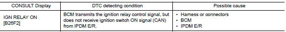
DTC CONFIRMATION PROCEDURE
1.PERFORM DTC CONFIRMATION PROCEDURE
1. Turn ignition switch ON, and wait for 2 seconds or more.
2. Check "Self-diagnosis result" with CONSULT.
Is DTC detected?
YES >> Go to PCS "Diagnosis Procedure".
NO >> Inspection End.
Diagnosis Procedure
Regarding Wiring Diagram information, refer to PCS "Wiring Diagram".
1.CHECK IPDM E/R SELF-DIAGNOSTIC RESULT
1. Turn ignition switch ON.
2. Erase the DTC of IPDM E/R.
3. Turn ignition switch OFF.
4. Turn ignition switch ON and check the DTC again.
Is DTC detected?
YES >> Repair or replace the malfunctioning part. Refer to BCS "DTC Index".
NO >> GO TO 2.
2.CHECK IGNITION RELAY-1 CONTROL SIGNAL (IPDM E/R)
1. Turn ignition switch OFF.
2. Check voltage between IPDM E/R harness connector and ground.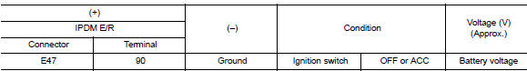
Is the inspection result normal?
YES >> Replace IPDM E/R.
NO >> GO TO 3.
3.CHECK IGNITION RELAY-1 CONTROL SIGNAL CIRCUIT - 1 (IPDM E/R)
1. Turn ignition switch OFF.
2. Disconnect BCM and IPDM E/R connectors.
3. Check continuity between IPDM E/R harness connector and ground.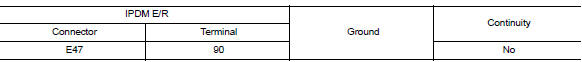
Is the inspection result normal?
YES >> GO TO 4.
NO >> Repair or replace harness.
4.CHECK IGNITION RELAY-1 CONTROL SIGNAL CIRCUIT - 2 (IPDM E/R)
1. Connect IPDM E/R connectors.
2. Check voltage between IPDM E/R harness connector and ground.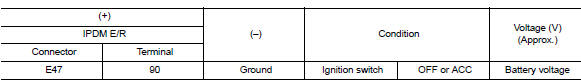
Is the inspection result normal?
YES >> Replace BCM. Refer to BCS "Removal and Installation".
NO >> Replace IPDM E/R.
 B26F1 Ignition relay
Other materials:
Fuel-filler door
Opener operation
The fuel-filler door release is located below the
instrument panel. To open the fuel-filler door, pull
the release. To lock, close the fuel-filler door
securely.
Fuel-filler cap
WARNING
Gasoline is extremely flammable and
highly explosive under certain conditions.
...
Malfunction indicator lamp
Component Function Check
1.CHECK MIL FUNCTION
Turn ignition switch ON.
Make sure that MIL lights up.
Is the inspection result normal?
YES >> INSPECTION END
NO >> Go to EC, "Diagnosis Procedure".
Diagnosis Procedure
1.CHECK DTC
Check that DTC UXXXX is not display ...
Categories
- Manuals Home
- Nissan Versa Owners Manual
- Nissan Versa Service Manual
- Video Guides
- Questions & Answers
- External Resources
- Latest Updates
- Most Popular
- Sitemap
- Search the site
- Privacy Policy
- Contact Us

0.0056