Nissan Versa (N17): Diagnosis system (AV Control unit)
Description
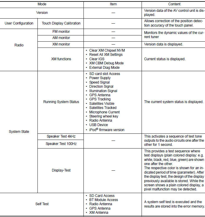
The AV control unit on board diagnosis performs the functions listed in the table below:
Perform CONSULT diagnosis if the AV control unit on board diagnosis does not start or the screen does not display anything.
On Board Diagnosis Function
METHOD OF STARTING
1. Turn the ignition ON.
2. Turn the audio system OFF.
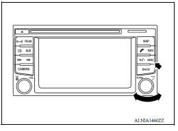
3. While pressing the MENU button, turn the TUNE-SCROLL dial counterclockwise 3 or more clicks, then clockwise 3 or more clicks, then counterclockwise 3 or more clicks. Shifting from current screen to previous screen is performed by pressing BACK button.
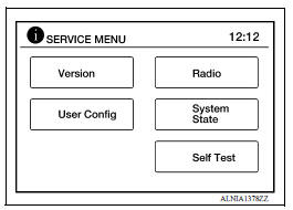
4. The trouble diagnosis initial screen is displayed, and Version, User Config, Radio, System State or Self Test can be selected.
CONSULT Function
CONSULT FUNCTIONS
CONSULT performs the following functions via communication with the AV
control unit. 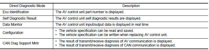
ECU IDENTIFICATION
The part number of AV control unit is displayed.
SELF DIAGNOSTIC RESULT
Refer to AV "DTC Index".
DATA MONITOR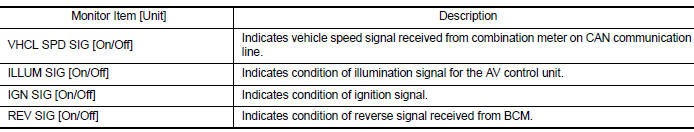
CONFIGURATION
Refer to AV "CONFIGURATION (AV CONTROL UNIT) : Description".
CAN DIAG SUPPORT MNTR
Refer to LAN "CAN Diagnostic Support Monitor".
ECU DIAGNOSIS INFORMATION
AV CONTROL UNIT
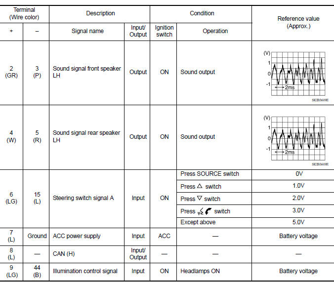
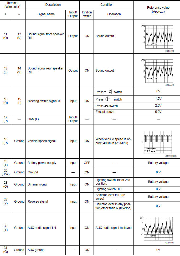
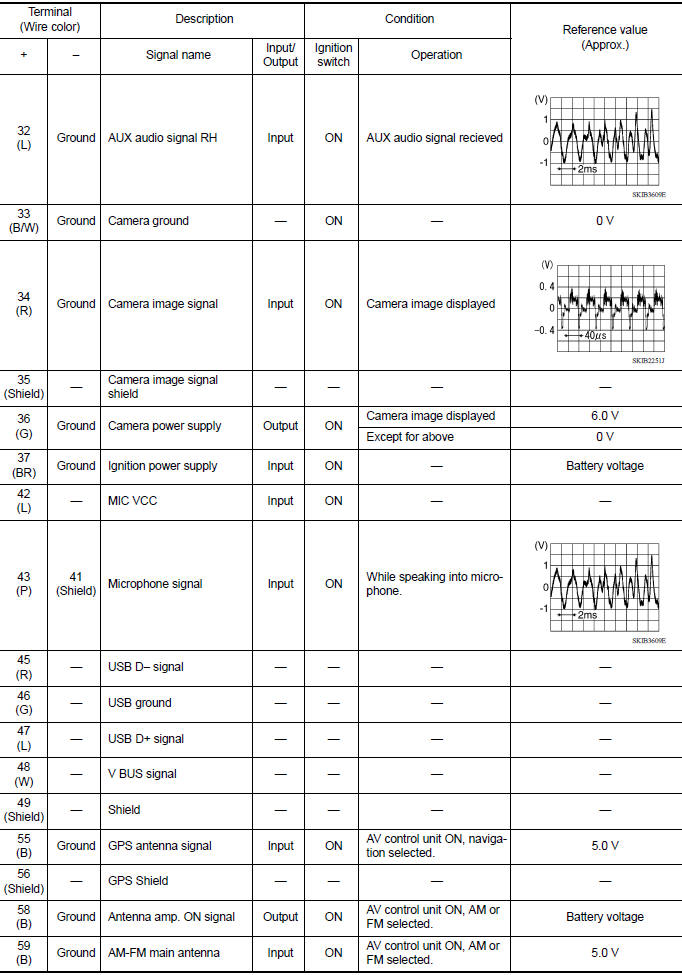
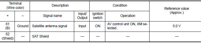
Reference Value
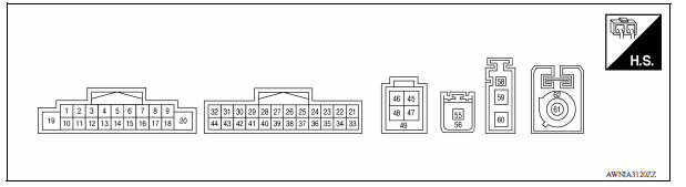
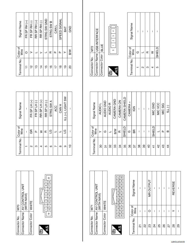
TERMINAL LAYOUT
PHYSICAL VALUES
DTC Index
| CONSULT Display | Reference Page |
| U1000: CAN COMM CIRCUIT | AV-180, "DTC Logic" |
| U1010: CONTROL UNIT (CAN) | AV-181, "DTC Logic" |
| U1217: BLUETOOTH MODULE | AV-182, "DTC Logic" |
| U1229: iPod CERTIFICATION | AV-183, "DTC Logic" |
| U122F: Digital broadcasting connection error | AV-184, "DTC Logic" |
| U1244: GPS ANTENNA CONN | AV-185, "DTC Logic" |
| U1258: XM ANTENNA CONN | AV-186, "DTC Logic" |
| U1263: USB OVERCURRENT | AV-187, "DTC Logic" |
| U1264: ANTENNA AMP TERMINAL | AV-188, "DTC Logic" |
| U12AA: Configuration Error | AV-189, "DTC Logic" |
| U12AC: Display Temperature too High | AV-190, "DTC Logic" |
| U12AD: ECU Temperature too High | AV-191, "DTC Logic" |
| U12AE: Internal Amplifier temperature Warning | AV-192, "DTC Logic" |
| U12AF: CD Mechanism Temperature Warning | AV-193, "DTC Logic" |
| U12B0: Supply Voltage Goes below 9V > 20s | AV-194, "DTC Logic" |
| U12B1: Supply Voltage Goes High > 16V for 20s | AV-195, "DTC Logic" |
| U1310: CONTROL UNIT (AV) | AV-196, "DTC Logic" |
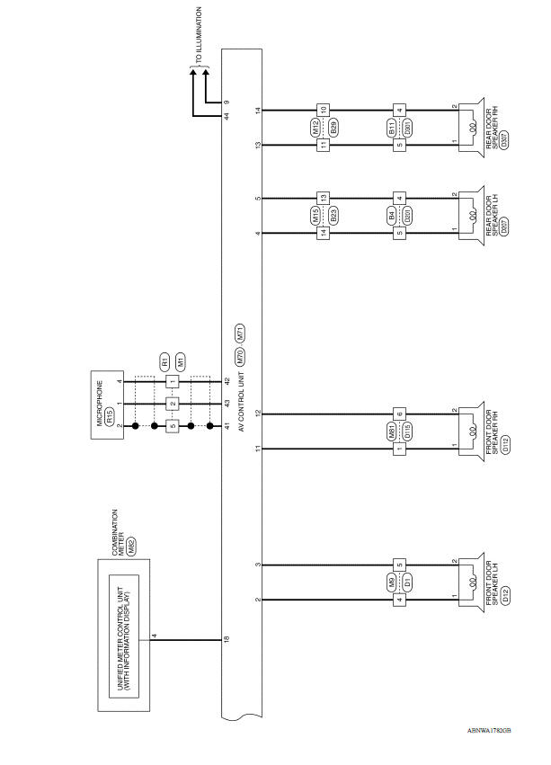
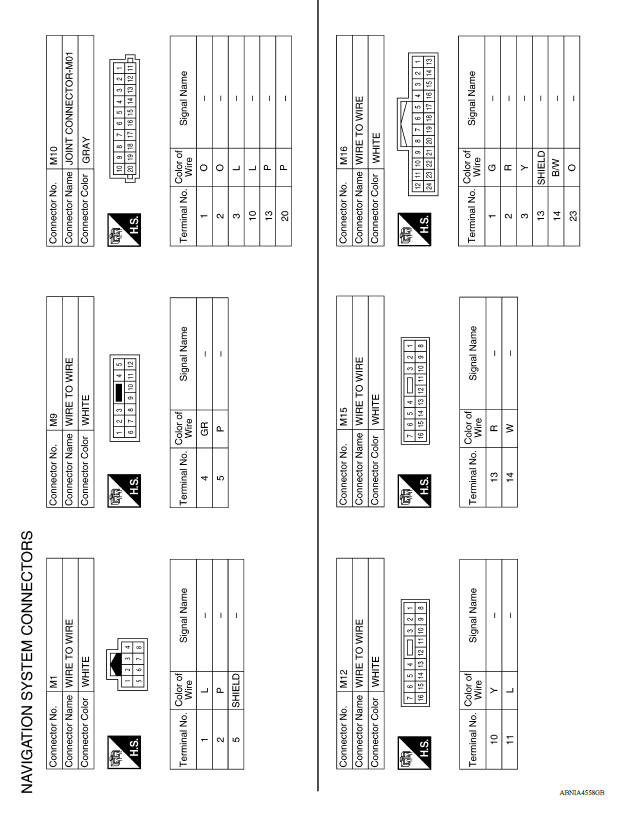
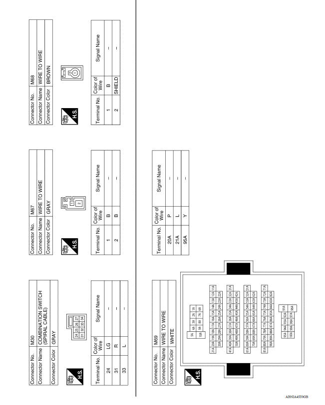
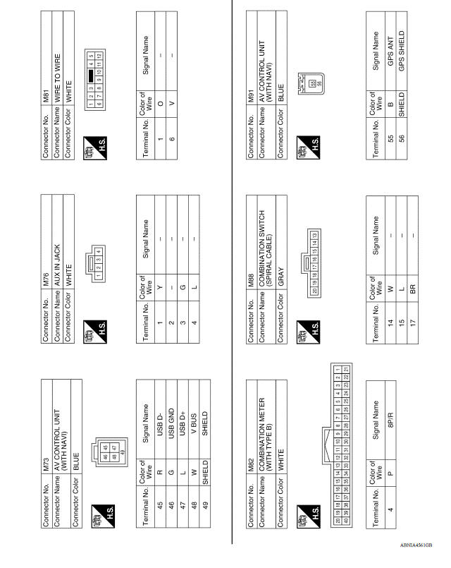
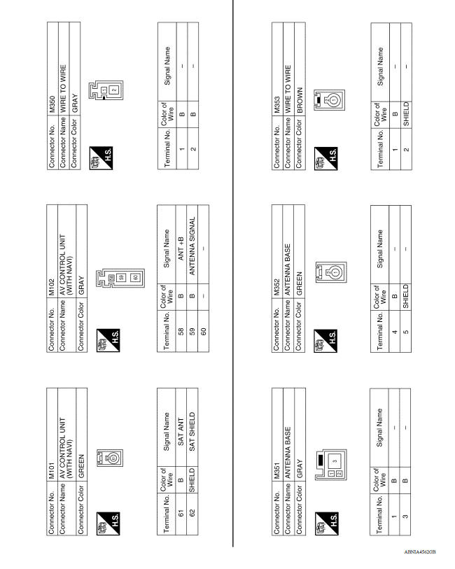
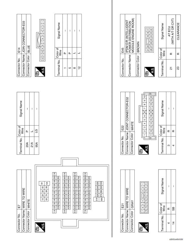
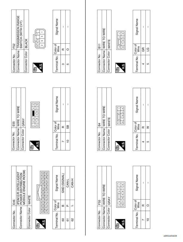
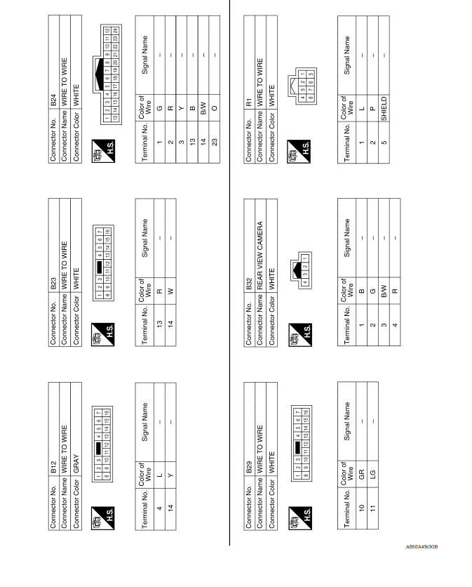
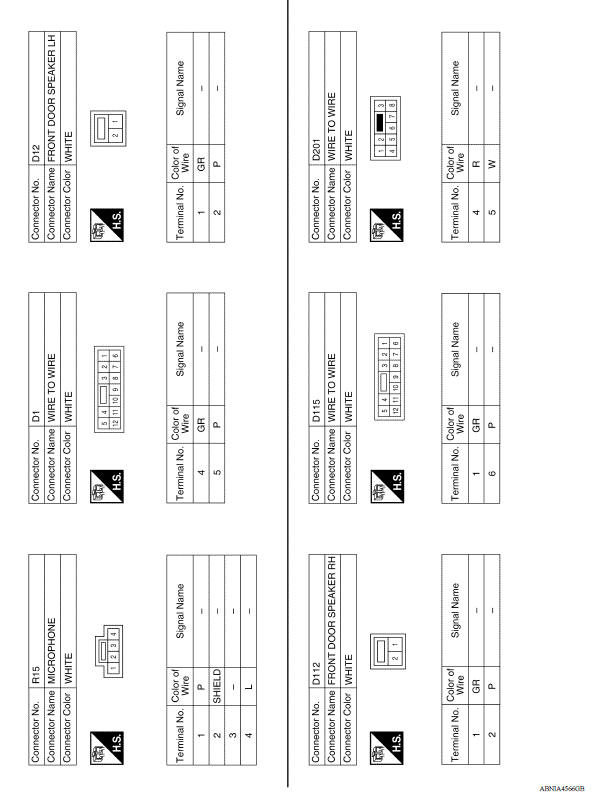
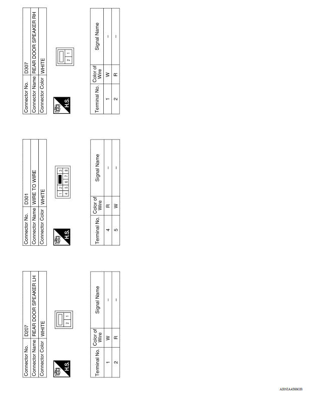
WIRING DIAGRAM
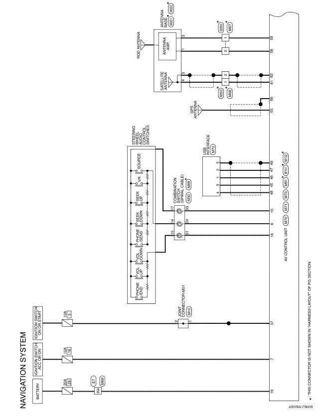
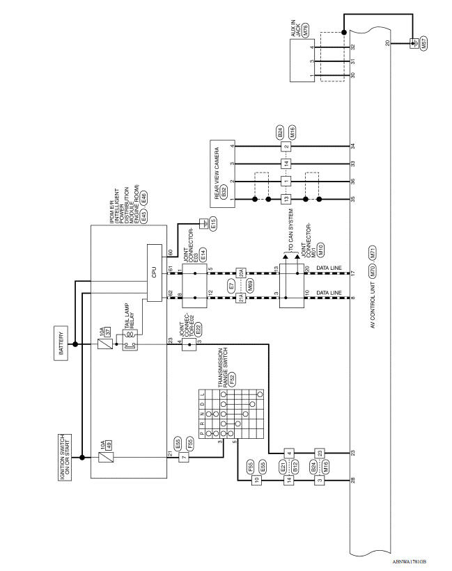
NAVIGATION SYSTEM
Wiring Diagram
BASIC INSPECTION
 System
System Diagram System Description AUDIO SYSTEM The audio system consists of the following components AV control unit with built-in display Front door speakers Rear door speakers Steer ...
Diagnosis and repair workflow
Work Flow OVERALL SEQUENCE DETAILED FLOW 1.GET INFORMATION FOR SYMPTOM Get detailed information from the customer about the symptom (the condition and the environment when the incident/ma ...
Other materials:
Fuel injector and fuel tube
Exploded View
1. Stud bolt 2. Oring (green) 3. Fuel injector (front) 4. Clip 5. Fuel
injector (rear) 6. Oring (black) 7. Fuel tube protector 8. Fuel tube 9. Clamp
10. Quick connector cap (engine side) 11. Fuel feed hose 12. Quick connector cap
(floor pipingside) 13. Fuel connector protect ...
EPS Warning lamp
Component Function Check
1.CHECK THE ILLUMINATION OF THE EPS WARNING LAMP
Check that the EPS warning lamp turns ON when ignition switch turns ON. Then,
EPS warning lamp turns
OFF after the engine is started.
Is the inspection result normal?
YES >> Inspection End.
NO >> Perform t ...
Categories
- Manuals Home
- Nissan Versa Owners Manual
- Nissan Versa Service Manual
- Video Guides
- Questions & Answers
- External Resources
- Latest Updates
- Most Popular
- Sitemap
- Search the site
- Privacy Policy
- Contact Us

0.0058