Nissan Versa (N17): Diagnosis and repair workflow
Work Flow
OVERALL SEQUENCE
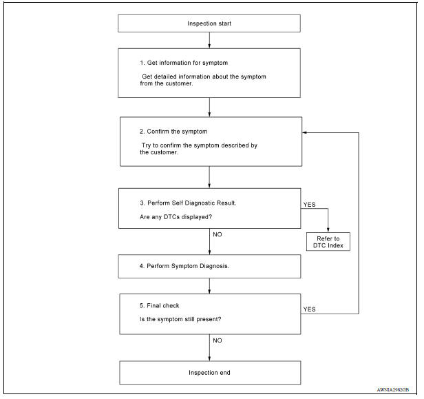
DETAILED FLOW
1.GET INFORMATION FOR SYMPTOM
Get detailed information from the customer about the symptom (the condition and the environment when the incident/malfunction occurred).
>> GO TO 2.
2.CONFIRM THE SYMPTOM
Try to confirm the symptom described by the customer. Verify relation between the symptom and the condition when the symptom is detected.
>> GO TO 3.
3.PERFORM SELF DIAGNOSTIC RESULT
1. Turn ignition switch ON and wait for 2 seconds or more.
2. Perform Self Diagnostic Result for MULTI AV.
Are any DTCs displayed?
YES >> Refer to AV "DTC Index".
NO >> GO TO 4.
4.PERFORM SYMPTOM DIAGNOSIS
Refer to AV "Symptom Table".
>> GO TO 5
5.FINAL CHECK
Refer to symptom described by the customer in step 1.
Is the symptom still present?
YES >> GO TO 2
NO >> Inspection End.
 Diagnosis system (AV Control unit)
Description The AV control unit on board diagnosis performs the functions listed in the table below: Perform CONSULT diagnosis if the AV control unit on board diagnosis does not start or t ...

Other materials:
P0732 2GR Incorrect ratio
Description
This malfunction is detected when the A/T does not shift into 2GR position as
instructed by TCM. This is not
only caused by electrical malfunction (circuits open or shorted) but by
mechanical malfunction such as control
valve sticking, improper solenoid valve operation, etc.
DTC ...
Oil pan
Exploded View
1. Transaxle assembly 2. Oil pan gasket 3. Magnet
4. Oil pan 5. Overflow tube 6. Drain plug gasket
7. Drain plug 8. Oil pan fitting bolt
Removal and Installation
REMOVAL
Remove the drain plug and overflow tube, and then drain the CVT fluid.WARNING:
CVT fluid can splash ...
Categories
- Manuals Home
- Nissan Versa Owners Manual
- Nissan Versa Service Manual
- Video Guides
- Questions & Answers
- External Resources
- Latest Updates
- Most Popular
- Sitemap
- Search the site
- Privacy Policy
- Contact Us

0.0052