Nissan Versa (N17): Diagnosis system (IPDM E/R)
Diagnosis Description
AUTO ACTIVE TEST
Description
In auto active test, the IPDM E/R sends a drive signal to the following systems to check their operation.
- Front wiper (LO, HI)
- Parking lamp
- License plate lamp
- Tail lamp
- Front fog lamp
- Headlamp (LO, HI)
- A/C compressor (magnet clutch)
- Cooling fan
Operation Procedure
NOTE: Never perform auto active test in the following conditions.
- Passenger door is open
- CONSULT is connected
1. Close the hood and lift the wiper arms from the windshield. (Prevent windshield damage due to wiper operation)
NOTE: When auto active test is performed with hood opened, sprinkle water on windshield beforehand.
2. Turn the ignition switch OFF.
3. Turn the ignition switch ON, and within 20 seconds, press the driver door switch 10 times. Then turn the ignition switch OFF.
4. Turn the ignition switch ON within 10 seconds. After that the horn sounds once and the auto active test starts.
5. After a series of the following operations is repeated 3 times, auto active test is completed.
NOTE:
- When auto active test has to be cancelled halfway through test, turn the ignition switch OFF.
- When auto active test is not activated, door switch may be the cause. Check door switch. Refer to DLK "Component Function Check".
Inspection in Auto Active Test
When auto active test is actuated, the following operation sequence is
repeated 3 times.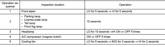
Concept of Auto Active Test
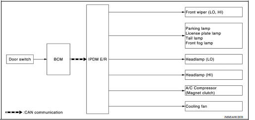
- IPDM E/R starts the auto active test with the door switch signals
transmitted by BCM via CAN communication.
Therefore, the CAN communication line between IPDM E/R and BCM is considered normal if the auto active test starts successfully.
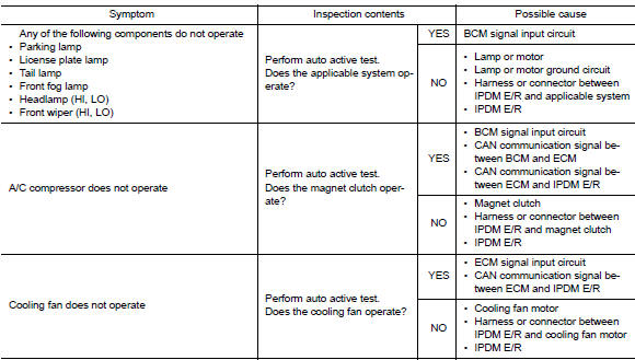
- The auto active test facilitates troubleshooting if any systems controlled by IPDM E/R cannot be operated.
Diagnosis Chart in Auto Active Test
CONSULT Function (IPDM E/R)
APPLICATION ITEM
CONSULT performs the following functions via CAN communication with IPDM E/R.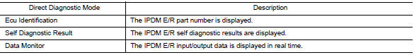
ECU IDENTIFICATION
The IPDM E/R part number is displayed.
SELF DIAGNOSTIC RESULT
Refer to PCS"DTC Index".
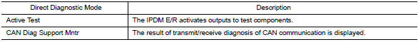
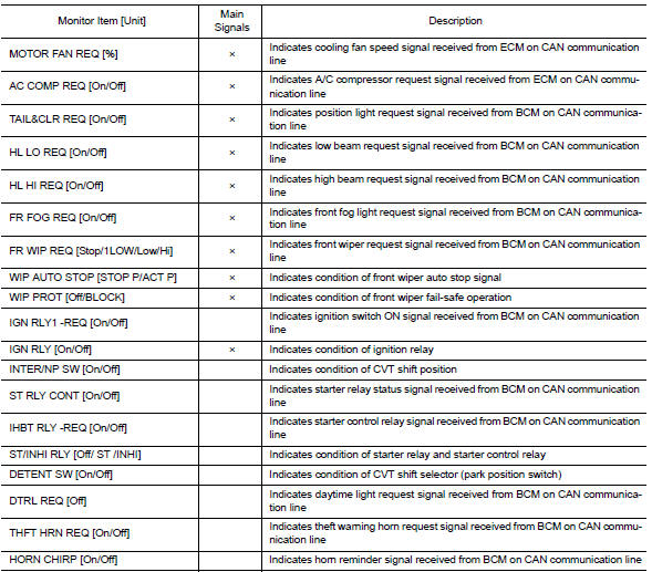
DATA MONITOR
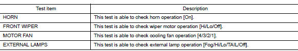
ACTIVE TEST
CAN DIAG SUPPORT MNTR
Refer to LAN "CAN Diagnostic Support Monitor".
ECU DIAGNOSIS INFORMATION
 System
RELAY CONTROL SYSTEM RELAY CONTROL SYSTEM : System Diagram RELAY CONTROL SYSTEM : System Description IPDM E/R activates the internal control circuit to perform the relay ON-OFF control acco ...
IPDM E/R (Intelligent power distribution
module engine room)
Reference Value VALUES ON THE DIAGNOSIS TOOL TERMINAL LAYOUT PHYSICAL VALUES *:M/T **:CVT or A/T ...
Other materials:
Fuel efficient driving tips
Follow these easy-to-use Fuel Efficient Driving
Tips to help you achieve the most fuel economy
from your vehicle.
1. Use Smooth Accelerator and Brake
Pedal Application
Avoid rapid starts and stops.
Use smooth, gentle accelerator and
brake application whenever possible.
Maintain constan ...
EVAP control system pressure sensor
Exploded View
1. EVAP control system pressure sensor 2. O-ring 3. EVAP canister
Removal and Installation
NOTE:
The EVAP canister system pressure sensor can be removed without removing the
EVAP canister.
REMOVAL
Remove the EVAP canister protector cover.
Disconnect EVAP canister purg ...
Categories
- Manuals Home
- Nissan Versa Owners Manual
- Nissan Versa Service Manual
- Video Guides
- Questions & Answers
- External Resources
- Latest Updates
- Most Popular
- Sitemap
- Search the site
- Privacy Policy
- Contact Us

0.006