Nissan Versa (N17): Cylinder block
Exploded View
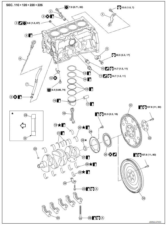
1. Crankshaft position sensor cover 2. Crankshaft position sensor (POS) 3. Oring 4. Drain plug 5. Cylinder block 6. Oil level gauge 7. Oil level gauge guide 8. Oring 9. Knock sensor 10. Oil temperature sensor 11. Oil pressure sensor 12. Oil jet 13. Top ring 14. Second ring 15. Oil ring 16. Piston 17. Piston pin 18. Connecting rod 19. Connecting rod bearing (upper) 20. Main bearing (upper) 21. Thrust bearing 22. Crankshaft key 23. Connecting rod bolt 24. Connecting rod cap 25. Connecting rod bearing (lower) 26. Main bearing (lower) 27. Crankshaft 28. Pilot converter (A/T and CVT models) 29. Signal plate 30. Rear oil seal 31. Drive plate (A/T and CVT models) 32. Reinforce plate (A/T and CVT models) 33. Flywheel (M/T models) 34. Main bearing cap 35. Main bearing cap bolt
Disassembly and Assembly
DISASSEMBLY
NOTE:
The following procedures explain how to disassemble the engine with the engine stand fastened to the bell housing. Some steps may be different if using a different type of engine stand.
- Remove cylinder head.
- Remove knock sensor.
CAUTION:
Carefully handle knock sensor avoiding shocks.
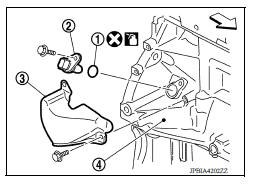
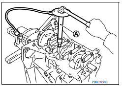
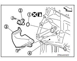
3. Remove the crankshaft position sensor cover (3), and then crankshaft position sensor (POS) (2).
(1) Oring
(4) Cylinder block
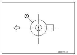
 : Engine front
CAUTION:
- Avoid impacts such as a dropping.
- Do not disassemble.
- Keep sensor away from metal particles.
- Do not place the sensor in a location where it is exposed to magnetism.
- Do not reuse Oring.
4. Remove oil pan (upper and lower).
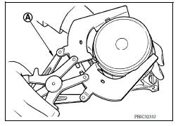
5. Remove piston and connecting rod assembly:
- Before removing piston and connecting rod assembly, check the connecting rod side clearance.
a. Position crankshaft pin corresponding to connecting rod to be removed onto the bottom dead center.
b. Remove connecting rod cap.
c. Using a hammer handle or similar tool, push piston and connecting rod assembly out through the cylinder head side.
CAUTION:
- Be careful not to damage mating surface with connecting rod cap.
- Be careful not to damage the cylinder wall or crankshaft pin.
6. Remove connecting rod bearings.
CAUTION:
Identify original positions for installation, and store the bearings without mixing them up.
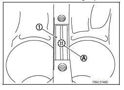
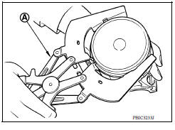
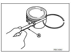
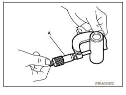
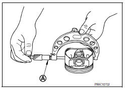
7. Remove piston rings from piston.
- Before removing piston rings, check the piston ring side clearance. Refer to EM103, "Inspection".
- Use a suitable tool) (A) as shown.
CAUTION:
- When removing piston rings, be careful not to damage the piston.
- Be careful not to damage piston rings by expanding them excessively.
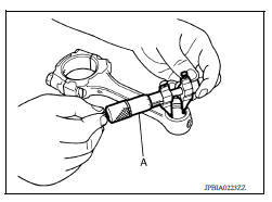
8. Remove piston from connecting rod.
- Use a Tools (A, B, C) and a press to remove the piston pin.
Tool Number (A) : KV10109730
(B) : KV10110310
(C) : ST13030020
CAUTION:
- Do not damage the piston and connecting rod.
- Do not reuse piston and piston pin after removing piston pin from connecting rod.
- The connecting rod is reusable.
NOTE:
The joint between the connecting rod and the piston pin is a press fit.
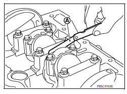
9. Remove the main bearing cap.
- Measure crankshaft end play before loosening main bearing cap bolts.
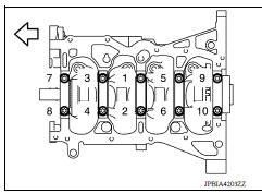
a. Loosen and remove bolts in several steps in reverse of the numerical order as shown.
 : Engine front
NOTE:
When removing or installing signal plate, use socket (size T40).
b. Remove the main bearing cap from the cylinder block while tapping lightly with a plastic hammer.
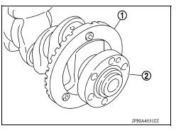
10. Remove crankshaft (2).
CAUTION:
- Be careful not damage or deform signal plate (1) mounted on crankshaft.
- When setting crankshaft on a flat floor surface, use a block of wood to avoid interference between signal plate and the floor surface.
- Do not remove signal plate unless it is necessary to do so.
NOTE:
When removing or installing signal plate, use socket (size T40).
11. Pull rear oil seal out from rear end of crankshaft.
12. Remove main bearing (upper and lower) and thrust bearings from cylinder block and main bearing caps.
CAUTION:
Identify original installation positions, and store the bearings without mixing them up.
13. Remove oil jets.
CAUTION:
Insert the dowel pin of oil jet into the cylinder block dowel pin hole to loosen the bolt.
ASSEMBLY
CAUTION:
Do not reuse Orings.
1. Fully airblow engine coolant and engine oil passages in cylinder block, cylinder bore and crankcase to remove any foreign material.
WARNING:
Use goggles to protect your eyes.
2. Install oil jets.
3. Install main bearings and thrust bearings:
a. Remove dust, dirt, and engine oil on the bearing mating surfaces of cylinder block.
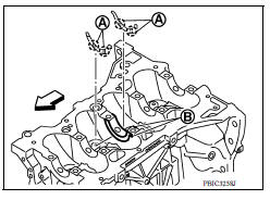
b. Install thrust bearings to the both sides of the No. 3 journal housing (B) on cylinder block.
 : Engine front
- Install thrust bearings with the oil groove (A) facing crankshaft arm (outside).
c. Install the main bearings paying attention to the direction.
- Before installing main bearings, apply new engine oil to the bearing surface (inside). Do not apply engine oil to the back surface, but thoroughly clean it.
- When installing, align main bearing to the center position of cylinder block and main bearing cap.
- Ensure the oil holes on cylinder block and oil holes (A) on the main bearings (1) are aligned.
NOTE:
For assembly, the center position can be visually identified.
- To install the main bearing, obtain a proper fit. Do not allow the main bearing to lie off the cylinder block chamfer.
- To install the main bearing, obtain a proper fit. Do not allow the main bearing to lie off bearing cap chamfer.
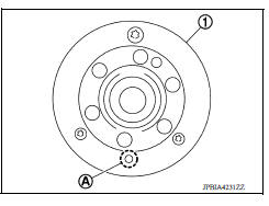
4. Install signal plate to crankshaft if removed.
a. Set the signal plate (1) with the flange facing toward the counterweight side (engine front side) to the crankshaft rear surface.
(A) : Dowel pin hole
b. After positioning crankshaft and signal plate with positioning dowel pin, tighten bolt.
NOTE:
Dowel pin of crankshaft and signal plate is provided as a set for each.
c. Remove dowel pin.
CAUTION:
Be sure to remove dowel pin.
5. Install crankshaft to cylinder block.
- While turning crankshaft by hand, check that it turns smoothly.
CAUTION:
Do not install rear oil seal at this time.
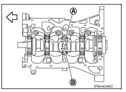
6. Install main bearing caps
- Install the main bearing cap while referring to the front mark (B) and the journal number stamp (A).
: Engine front
NOTE:
Main bearing cap cannot be replaced as a single part, because it is machined together with cylinder block.
7. Tighten main bearing cap bolts in numerical order as shown with the following steps:
: Engine front
a. Apply new engine oil to threads and seat surfaces of the bolts.
b. Tighten main bearing cap bolts in numerical order.
Main bearing cap bolts : 32.4 N*m (3.3 kgm, 24 ftlb)
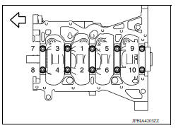
c. Turn main bearing cap bolts 60 degrees clockwise (angle tightening) in numerical order as shown.
CAUTION:
Check and confirm the tightening angle by using the Tool (A) or protractor. Avoid judgment by visual inspection without the Tool.
Tool number : KV10112100 (BT8653A)
- After installing the main bearing cap bolts, check that crankshaft can be rotated smoothly by hand.
- Check crankshaft end play.
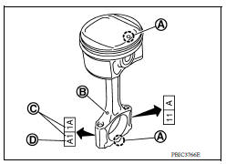
8. Install piston to connecting rod with the following procedure:
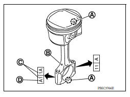
a. Set so that the front mark (A) on the piston head and the cylinder number (C) are in the position as shown.
(B) : Oil hole
(D) : Connecting rod big end grade
NOTE:
The symbols without notes are for manufacturing.
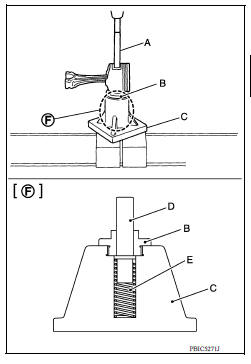
b. Pressfit the piston pin using the Tools (A, B, C, D, E).
Tool number (A) : KV10109730
(B) : KV10110310
(C) : ST13030020
(D) : KV10114120
(E) : ST13030030
(F) : Detail
CAUTION:
Pressfit the piston so as not to damage it.
NOTE:
The joint between the connecting rod and the piston pin is a press fit.
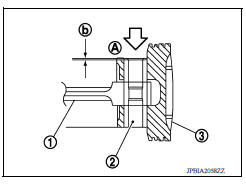
- Pressfit the piston pin (2) from piston surface (A) to the depth of 2.35 mm (0.092 in) (b).
(1) : Connecting rod
 : Pressfit direction
- After finishing work, check that the piston (3) moves freely.
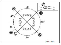
9. Using suitable tool (A), install piston rings.
CAUTION:
- Be careful not to damage piston.
- Be careful not to damage piston rings by expanding them excessively.
- Position each ring with the gap as shown referring to the piston front mark (B).
(A) : Oil ring upper or lower rail gap (either of them)
(C) : Second ring and oil ring spacer gap
(D) : Top ring gap
- Install second ring with the stamped mark (E) facing upward.
Stamped mark:
Top ring : 1R
Second ring : 2R
10. Install connecting rod bearings to connecting rod and connecting rod cap.
- When installing connecting rod bearings, apply new engine oil to the bearing surface (inside). Do not apply engine oil to the back surface, but thoroughly clean it.
- Install the bearing in the center position.
NOTE:
There is no stopper tab.
- Check that the oil holes on connecting rod and connecting rod bearing are aligned.
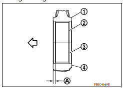
- Install the connecting rod in the dimension (A) as shown.
(1) : Connecting rod
(2) : Connecting rod bearing (upper)
(3) : Connecting rod bearing (lower)
(4) : Connecting rod cap
(A) : 1.7 2.1 mm (0.067 0.083 in)
 : Engine front
NOTE:
Install the connecting rod bearing in the center position with the dimension as shown. For service operation, the center position can be checked visually.
11. Install piston and connecting rod assembly to crankshaft.
- Position crankshaft pin corresponding to connecting rod to be installed onto the bottom dead center.
- Apply new engine oil sufficiently to the cylinder bore, piston and crankshaft pin.
- Match the cylinder position with the cylinder number on connecting rod to install.
- Using Tool (A) or suitable tool, install piston with the front mark on the piston head facing the front of the engine.
CAUTION:
- Be careful not to damage mating surface with connecting rod cap.
- Be careful not to damage the cylinder wall or crankshaft pin.
Tool number : EM03470000
12. Install connecting rod cap.
- Match the stamped cylinder number marks (C) on connecting rod with those on connecting rod cap to install.
(A) : Front mark
(B) : Oil hole
(D) : Connecting rod big end grade
13. Inspect outer diameter of connecting rod bolts.
14. Tighten connecting rod bolt:
a. Apply new engine oil to the threads and seats of connecting rod bolts.
b. Tighten connecting rod bolts in several steps.
Connecting rod bolts : 27.4 N*m (2.8 kgm, 20 ftlb)
c. Completely loosen connecting rod bolts.
Connecting rod bolts : 0 N*m (0 kgm, 0 ftlb)
d. Tighten connecting rod bolts in several steps.
Connecting rod bolts : 19.6 N*m (2.0 kgm, 14 ftlb)
e. Then turn all connecting rod bolts 60 degrees clockwise (angle tightening).
CAUTION:
Check and confirm the tightening angle by using the Tool (A) or protractor. Avoid judgement by visual inspection without the Tool.
Tool number : KV10112100 (BT8653A)
- After tightening connecting rod bolt, check that crankshaft rotates smoothly.
- Check the connecting rod side clearance.
15. Install oil pan (upper).
NOTE:
Install the rear oil seal after installing the oil pan (upper).
16. Install rear oil seal.
17. Install flywheel (M/T models) or drive plate (A/T and CVT models).
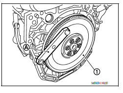
M/T models
- Secure crankshaft with a stopper plate (A) and tighten bolts crosswise over several times.
(1) :Flywheel
Tool number : KV11105210 (J44716)
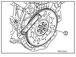
A/T and CVT models
- Secure crankshaft with a stopper plate (A) and tighten bolts crosswise over several times
(1) :Drive plate
Tool number : KV11105210 (J44716)
CAUTION:
Be careful not to damage or scratch and contact surface for clutch disc of flywheel.
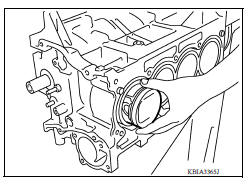
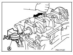
18. Install knock sensor (1).
: Engine front
- Install connectors so that they are positioned toward the rear of the engine.
CAUTION:
- Do not tighten bolt while holding the connector.
- If any impact by dropping is applied to knock sensor, replace it with a new one.
NOTE:
- Check that there is no foreign material on the cylinder block mating surface and the back surface of knock sensor.
- Check that knock sensor does not interfere with other parts.
19. Install crankshaft position sensor (POS) (2) using a new Oring (1) and then install the crankshaft position sensor cover (3) on the cylinder block (4).
- Tighten bolts with sensor inserted completely.
: Engine front
CAUTION:
- Avoid impacts such as a dropping.
- Do not disassemble.
- Keep sensor away from metal particles.
- Do not place the sensor in a location where it is exposed to magnetism.
- Do not reuse Oring.
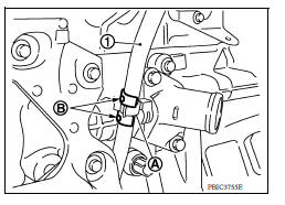
20. For the oil level gauge guide (1), secure in position (B) shown to the water inlet clip (A) after inserting to the cylinder block side.
21. Assembly of the remaining components is in the reverse order of disassembly.
Inspection
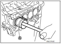
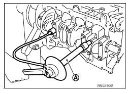
CRANKSHAFT END PLAY
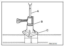
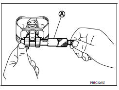
- Measure the clearance between thrust bearings and crankshaft arm when crankshaft is moved fully forward or backward with a suitable tool (A).
- If the measured value exceeds the limit, replace thrust bearings, and measure again. If it still exceeds the limit, replace crankshaft also.
CONNECTING ROD SIDE CLEARANCE
- Measure the side clearance between connecting rod and crankshaft arm with a suitable tool (A).
- If the measured value exceeds the limit, replace connecting rod, and measure again. If it still exceeds the limit, replace crankshaft also.
PISTON TO PISTON PIN OIL CLEARANCE
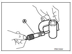
Piston Pin Hole Diameter Measure the inner diameter of piston pin hole with an suitable tool (A).
Piston Pin Outer Diameter Measure the outer diameter of piston pin with a suitable tool (A).
Piston to Piston Pin Oil Clearance (Piston to piston pin oil clearance) = (Piston pin hole diameter) - (Piston pin outer diameter)
- If oil clearance is out of the standard, replace piston and piston pin assembly.
- When replacing piston and piston pin assembly.
NOTE:
- Piston is available together with piston pin as assembly.
- Piston pin (piston pin hole) grade is provided only for the parts installed at the factory. For service parts, no grades can be selected. Only grade "0" is available.
PISTON RING SIDE CLEARANCE
- Measure the side clearance of piston ring and piston ring groove with a suitable tool (A).
- If the measured value exceeds the limit, replace piston ring, and measure again. If it still exceeds the limit, replace piston also.
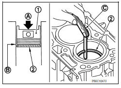
PISTON RING END GAP
- Check that cylinder bore inner diameter is within specification. Refer to "PISTON TO CYLINDER BORE CLEARANCE".
- Lubricate piston (1) and piston ring (2) with new engine oil and then insert (A) piston ring until middle of cylinder (B) with piston, and measure piston ring end gap with a feeler gauge (C).
- If the measured value exceeds the limit, replace piston ring, and measure again. If it still exceeds the limit, replace cylinder block.
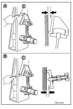
CONNECTING ROD BEND AND TORSION
- Check with a connecting rod aligner.
(A) : Bend
(B) : Torsion
(C) : Feeler gauge
- If it exceeds the limit, replace connecting rod assembly.
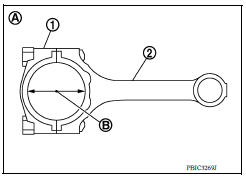
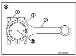
CONNECTING ROD BIG END DIAMETER
- Install connecting rod cap (1) without connecting rod bearing installed, and tightening connecting rod cap bolts to the specified torque.
(2) : Connecting rod
(A) : Example
(B) : Measuring direction of inner diameter
- Measure the inner diameter (B) of connecting rod big end with a suitable tool.
- If out of the standard, replace connecting rod assembly.
CONNECTING ROD BUSHING OIL CLEARANCE
Connecting Rod Bushing Inner Diameter Measure the inner diameter of connecting rod bushing with a suitable tool (A).
Piston Pin Outer Diameter Measure the outer diameter of piston pin with a micrometer (A).
Connecting Rod Bushing Oil Clearance (Connecting rod bushing oil clearance) = (Connecting rod bushing inner diameter) - (Piston pin outer diameter)
- If the measured value is out of the standard range, replace connecting rod assembly and/or piston and piston pin assembly.
- If replacing piston and piston pin assembly.
- If replacing connecting rod assembly.
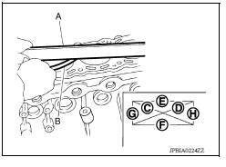
CYLINDER BLOCK TOP SURFACE DISTORTION
- Using a scraper, remove gasket on the cylinder block surface, and also remove engine oil, scale, carbon, or other contamination.
CAUTION:
Be careful not to allow gasket particles to enter engine oil or engine coolant passages.
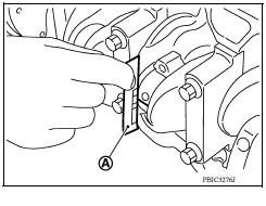
- Measure the distortion on the cylinder block upper face at different points in six directions with a suitable tool (A) and (B).
- If it exceeds the limit, replace cylinder block.
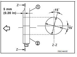
MAIN BEARING HOUSING INNER DIAMETER
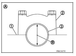
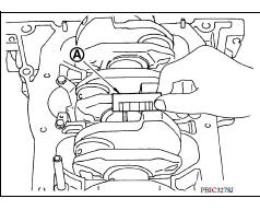
- Install main bearing cap without main bearings installed, and tighten main bearing cap bolts to the specified torque.
- Measure the inner diameter of main bearing housing with a suitable tool.
- Measure the position shown [5 mm (0.20 in)] backward from main bearing housing front side in the 2 directions as shown. The smaller one is the measured value.
(1) : Cylinder block
(2) : Main bearing cap
 : Engine front
- If out of the standard, replace cylinder block and main bearing caps assembly.
NOTE:
Main bearing caps cannot be replaced individually, because they are machined together with cylinder block.
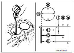
PISTON TO CYLINDER BORE CLEARANCE
Cylinder Bore Inner Diameter
- Using a suitable tool, measure the cylinder bore for wear, outofround and taper at six different points on each cylinder. [(A) and (B) directions at (C), (D), and (E)] [(A) is in longitudinal direction of engine]
(f) : 10 mm (0.39 in)
(g) : 60 mm (2.36 in)
(h) : 124 mm (4.88 in)
NOTE:
When determining cylinder bore grade, measure the cylinder bore (B) direction at (D) position.
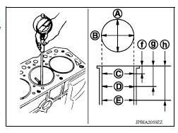
- If the measured value exceeds the limit, or if there are scratches and/or seizure on the cylinder inner wall, replace cylinder block.
NOTE:
Oversize piston is not available.
Piston Skirt Diameter Measure the outer diameter of piston skirt with a suitable tool (A).
Piston to Cylinder Bore Clearance Calculate by piston skirt diameter and cylinder bore inner diameter [direction (B), position (D)].
(A) : Direction A
(C) : Position C
(E) : Position E
(f) : 10 mm (0.39 in)
(g) : 60 mm (2.36 in)
(h) : 124 mm (4.88 in)
(Clearance) = (Cylinder bore inner diameter) - (Piston skirt diameter)
- If it exceeds the limit, replace piston and piston pin assembly and/or cylinder block.
CRANKSHAFT MAIN JOURNAL DIAMETER
- Measure the outer diameter of crankshaft main journals with a suitable tool (A).
- If out of the standard, measure the main bearing oil clearance.
Then use undersize bearing.
CRANKSHAFT PIN JOURNAL DIAMETER
- Measure the outer diameter of crankshaft pin journal with a suitable tool.
- If out of the standard, measure the connecting rod bearing oil clearance.
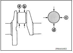
OUTOFROUND AND TAPER OF CRANKSHAFT
-
Measure the dimensions at four different points as shown on each main journal and pin journal with a suitable tool.
-
Outofround is indicated by the difference in dimensions between (a) and (b) at (c) and (d).
-
Taper is indicated by the difference in dimension between (c) and (d) at (a) and (b).
-
If the measured value exceeds the limit, correct or replace crankshaft.
-
If corrected, measure the bearing oil clearance of the corrected main journal and/or pin journal. Then select main bearing and/or connecting rod bearing.
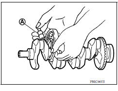
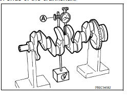
CRANKSHAFT RUNOUT
- Place a Vblock on a precise flat table to support the journals on both ends of the crankshaft.
- Place a suitable tool (A) straight up on the No. 3 journal.
- While rotating crankshaft, read the movement of the pointer on the suitable tool. (Total indicator reading)
- If it exceeds the limit, replace crankshaft.
CONNECTING ROD BEARING OIL CLEARANCE
Method by Calculation
- Install connecting rod bearings (2) to connecting rod (3) and connecting rod cap (1), and tighten connecting rod cap bolts to the specified torque.
(A) : Example
(B) : Inner diameter measuring direction
- Measure the inner diameter of connecting rod bearing with a suitable
tool.
(Bearing oil clearance) = (Connecting rod bearing inner diameter) - (Crankshaft pin journal diameter)
- If clearance exceeds the limit, select proper connecting rod bearing according to connecting rod big end diameter and crankshaft pin journal diameter to obtain specified bearing oil clearance.
Method of Using Plastigage
- Remove engine oil and dust on crankshaft pin and the surfaces of each bearing completely.
- Cut a plastigage slightly shorter than the bearing width, and place it in crankshaft axial direction, avoiding oil holes.
- Install connecting rod bearings to connecting rod and cap, and tighten connecting rod cap bolts to the specified torque.
CAUTION:
Do not rotate crankshaft.
- Remove connecting rod cap and bearing, and using the scale (A) on the plastigage bag, measure the plastigage width.
NOTE:
The procedure when the measured value exceeds the limit is same as that described in the "Method by Calculation".
MAIN BEARING OIL CLEARANCE
Method by Calculation
- Install main bearings (3) to cylinder block (1) and main bearing cap (2), and tighten main bearing cap bolts to the specified torque.
(A) : Example
(B) : Inner diameter measuring direction
- Measure the inner diameter (B) of main bearing (3) with a suitable
tool.
(Bearing oil clearance) = (Main bearing inner diameter) - (Crankshaft main journal diameter)
- If clearance exceeds the limit, select proper main bearing according to main bearing inner diameter and crankshaft main journal diameter to obtain specified bearing oil clearance.
Method of Using Plastigage
- Remove engine oil and dust on crankshaft main journal and the surfaces of each bearing completely.
- Cut a plastigage slightly shorter than the bearing width, and place it in crankshaft axial direction, avoiding oil holes.
- Install main bearings to cylinder block and main bearing cap, and tighten main bearing cap bolts to the specified torque.
CAUTION:
Do not rotate crankshaft.
- Remove main bearing cap and bearings, and using the scale (A) on the plastigage bag, measure the plastigage width.
NOTE:
The procedure when the measured value exceeds the limit is same as that described in the "Method by Calculation".
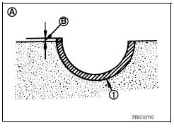
MAIN BEARING CRUSH HEIGHT
- When main bearing cap is removed after being tightened to the specified torque with main bearings (1) installed, the tip end of bearing must protrude (B).
(A) : Example
Standard : There must be crush height.
- If the standard is not met, replace main bearings.
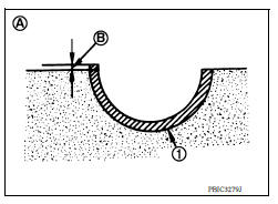
CONNECTING ROD BEARING CRUSH HEIGHT
- When connecting rod cap is removed after being tightened to the specified torque with connecting rod bearings (1) installed, the tip end of bearing must protrude (B).
(A) : Example
Standard : There must be crush height.
- If the standard is not met, replace connecting rod bearings.
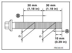
MAIN BEARING CAP BOLT OUTER DIAMETER
- Measure the outer diameters (d1) and (d2) at two positions as shown.
(A) : (d1) measuring position
(B) : (d2) measuring position
- If reduction appears in places other than (B) range, regard it as (d2).
Limit [(d1) - (d2)]: 0.2 mm (0.0078 in)
- If it exceeds the limit (a large difference in dimensions), replace main bearing cap bolt with a new one.
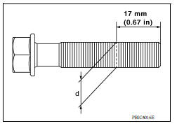
CONNECTING ROD CAP BOLT OUTER DIAMETER
- Measure the outer diameter (d) at position as shown.
- If reduction appears in a position other than (d), regard it
Limit: 7.75 mm (0.3051 in)
- When (d) is less than the limit (when it becomes thinner), replace connecting rod cap bolt with a new one.
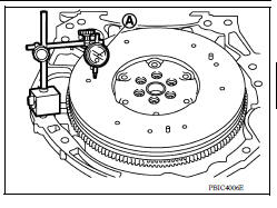
FLYWHEEL DEFLECTION (M/T models)
- Measure the deflection of flywheel contact surface to torque with a suitable tool (A).
- Measure the deflection at 210 mm (8.27 in) diameter.
Limit : 0.45 mm (0.0177 in) or less.
- If measured value is out of the standard, replace flywheel.
- If a trace of burn or discoloration is found on the surface, clean it with sandpaper.
CAUTION:
When measuring, keep magnetic fields (such as dial indicator stand) away from signal plate of the rear end of crankshaft.
 Oil pan (upper) and oil strainer
Exploded View 1. Rear oil seal 2. Oring 3. Oil pan (upper) 4. Oil pump chain tensioner (for oil pump drive chain) 5. Oil pump drive chain 6. Crankshaft key 7. Crankshaft sprocket 8. Oil pump ...
How to select piston and bearing
Description Selection points Selection parts Selection items Selection methods Between cylinder block and crankshaft Main bearing Main bearing grade (bearing thic ...
Other materials:
Engine stand setting
Setting
NOTE:
The following procedures explain how to disassemble the engine with the engine
stand fastened to the bell
housing. Some steps may be different if using a different type of engine stand.
1. Install engine to engine stand:
a. Rem ...
Preparation
Special Service Tools
The actual shapes of KentMoore tools may differ from those of special
service tools illustrated here.
Tool number
(KentMoore No.)
Tool name
Description
ST25051001
(J256951)
Oil pressure gauge &nbs ...
Categories
- Manuals Home
- Nissan Versa Owners Manual
- Nissan Versa Service Manual
- Video Guides
- Questions & Answers
- External Resources
- Latest Updates
- Most Popular
- Sitemap
- Search the site
- Privacy Policy
- Contact Us

0.0057