Nissan Versa (N17): DLC Branch line circuit
Diagnosis Procedure
1.CHECK CONNECTOR
1. Turn the ignition switch OFF.
2. Disconnect the battery cable from the negative terminal.
3. Check the terminals and connectors of the data link connector for damage, bend and loose connection (connector side and harness side).
Is the inspection result normal?
YES >> GO TO 2.
NO >> Repair the terminal and connector.
2.CHECK HARNESS FOR OPEN CIRCUIT
Check the resistance between the data link connector terminals.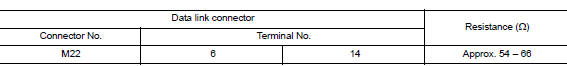
Is the measurement value within the specification?
YES (Present error)>>Check CAN system type decision again.
YES (Past error)>>Error was detected in the data link connector branch line circuit.
NO >> Repair the data link connector branch line.
 A-BAG Branch line circuit
Diagnosis Procedure WARNING: Always observe the following items for preventing accidental activation. Before servicing, turn ignition switch OFF, disconnect battery negative terminal, and w ...
EPS Branch line circuit
Diagnosis Procedure 1.CHECK CONNECTOR 1. Turn the ignition switch OFF. 2. Disconnect the battery cable from the negative terminal. 3. Check the terminals and connectors of the EPS control unit f ...
Other materials:
Oil cooler
Exploded View
1. Radiator hose (upper) 2. Hose clamp 3. Radiator hose (lower)
4. Hose clamp 5. Water hose 6. Oil cooler
7. Connector bolt 8. Water hose 9. Oring
A. To radiator (upper side) B. To radiator (lower side) 10. Relief valve
Removal and Installation
REMOVAL
NOTE:
When removing co ...
Combination switch output circuit
Diagnosis Procedure
Regarding Wiring Diagram information, refer to BCS "Wiring Diagram".
1.CHECK OUTPUT 1 - 5 CIRCUIT FOR OPEN
1. Turn ignition switch OFF.
2. Disconnect BCM and combination switch connectors.
3. Check continuity between BCM connector and combination switch connector.
...
Categories
- Manuals Home
- Nissan Versa Owners Manual
- Nissan Versa Service Manual
- Video Guides
- Questions & Answers
- External Resources
- Latest Updates
- Most Popular
- Sitemap
- Search the site
- Privacy Policy
- Contact Us

0.0051