Nissan Versa (N17): EPS Branch line circuit
Diagnosis Procedure
1.CHECK CONNECTOR
1. Turn the ignition switch OFF.
2. Disconnect the battery cable from the negative terminal.
3. Check the terminals and connectors of the EPS control unit for damage, bend and loose connection (unit side and connector side).
Is the inspection result normal?
YES >> GO TO 2.
NO >> Repair the terminal and connector.
2.CHECK HARNESS FOR OPEN CIRCUIT
1. Disconnect the connector of EPS control unit.
2. Check the resistance between the EPS control unit harness connector
terminals.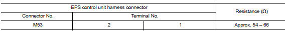
Is the measurement value within the specification?
YES >> GO TO 3.
NO >> Repair the EPS control unit branch line.
3.CHECK POWER SUPPLY AND GROUND CIRCUIT
Check the power supply and the ground circuit of the EPS control unit. Refer to STC "Diagnosis Procedure".
Is the inspection result normal?
YES (Present error)>>Replace the EPS control unit. Refer to STC"Removal and Installation".
YES (Past error)>>Error was detected in the EPS control unit branch line.
NO >> Repair the power supply and the ground circuit.
 DLC Branch line circuit
Diagnosis Procedure 1.CHECK CONNECTOR 1. Turn the ignition switch OFF. 2. Disconnect the battery cable from the negative terminal. 3. Check the terminals and connectors of the data link connector ...
M&A Branch line circuit
Diagnosis Procedure 1.CHECK CONNECTOR 1. Turn the ignition switch OFF. 2. Disconnect the battery cable from the negative terminal. 3. Check the terminals and connectors of the combination meter fo ...
Other materials:
Interior lights
The interior light has a three-position switch and
operates regardless of ignition switch position.
When the switch is in the ON position 1 , the
interior lights illuminate, regardless of door position.
The lights will go off after a period of time
unless the ignition switch is placed i ...
P0712 Transmission fluid temperature
sensor A
DTC Logic
DTC DETECTION LOGIC
DTC
Trouble diagnosis name
DTC detection condition
Possible causes
P0712
Transmission Fluid Temperature
Sensor A Circuit Low
The CVT fluid temperature identified by the
TCM is 180C (356F) or more continuously
for 5 seconds or ...
Categories
- Manuals Home
- Nissan Versa Owners Manual
- Nissan Versa Service Manual
- Video Guides
- Questions & Answers
- External Resources
- Latest Updates
- Most Popular
- Sitemap
- Search the site
- Privacy Policy
- Contact Us

0.0044