Nissan Versa (N17): DLC Branch line circuit
Diagnosis Procedure
1.CHECK CONNECTOR
1. Turn the ignition switch OFF.
2. Disconnect the battery cable from the negative terminal.
3. Check the terminals and connectors of the data link connector for damage, bend and loose connection (connector side and harness side).
Is the inspection result normal?
YES >> GO TO 2.
NO >> Repair the terminal and connector.
2.CHECK HARNESS FOR OPEN CIRCUIT
Check the resistance between the data link connector terminals.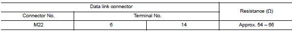
Is the measurement value within the specification?
YES (Present error)>>Check CAN system type decision again.
YES (Past error)>>Error was detected in the data link connector branch line circuit.
NO >> Repair the data link connector branch line.
 A-BAG Branch line circuit
Diagnosis Procedure WARNING: Always observe the following items for preventing accidental activation. Before servicing, turn ignition switch OFF, disconnect battery negative terminal, and wai ...
EPS Branch line circuit
Diagnosis Procedure 1.CHECK CONNECTOR 1. Turn the ignition switch OFF. 2. Disconnect the battery cable from the negative terminal. 3. Check the terminals and connectors of the EPS control unit for ...
Other materials:
Brake lining
BRAKE LINING : Inspection and Adjustment
INSPECTION
Brake Lining
Remove plug from back plate. Refer to BR "Exploded View".
Check brake lining wear thickness (A) from an inspection hole
on back plate. Check using a scale necessary.
(A) : Refer to BR "Rear Drum Brake&quo ...
Pedal vibration or ABS operation
sound occurs
Diagnosis Procedure
CAUTION:
Under the following conditions, ABS is activated and vibration is felt when
brake pedal is lightly
depressed (just place a foot on it). However, this is normal.
When shifting gears
When driving on slippery road
During cornering at high speed
When passing o ...
Categories
- Manuals Home
- Nissan Versa Owners Manual
- Nissan Versa Service Manual
- Video Guides
- Questions & Answers
- External Resources
- Latest Updates
- Most Popular
- Sitemap
- Search the site
- Privacy Policy
- Contact Us

0.0059