
Nissan Versa (N17): Door assembly
Door assembly : Removal and Installation
CAUTION:
- Use two people when removing or installing front door due to its heavy weight
- When removing and installing front door assembly, support the door using a suitable tool.
- Use shops cloths to protect surrounding components from damage during removal and installation of front door assembly.
REMOVAL
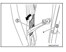
1. Remove front door harness grommet (1) and then pull out the harness from the vehicle (2).
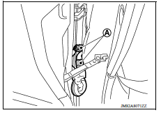
2. Disconnect the harness connectors (A) from front door assembly.
3. Remove door check link bolt (body side).
4. Remove door hinge nuts (door side) and front door assembly.
INSTALLATION
Installation is in the reverse order of removal.
CAUTION:
- Apply anticorrosive agent onto the hinge mating surface.
- After installation, check front door open/close, lock/unlock operation.
- Check door hinge rotating point for poor lubrication. If necessary, apply a suitable multi-purpose grease.
- After installation, perform the front door adjustment procedure. Refer to DLK "DOOR ASSEMBLY : Adjustment".
- After adjusting, apply touch-up paint (body color) onto the head of door hinge nuts.
Door assembly : Adjustment
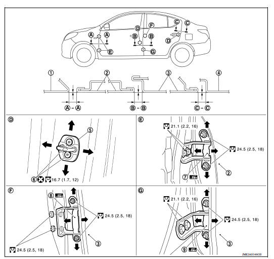
1. Front fender 2. Front door 3. Rear door 4. Body side outer 5. Door striker 6. Striker bolt 7. Front door hinge 8. Rear door hinge (upper) 9. Rear door hinge (lower)
Check the clearance and surface height between front door and each part by visual inspection and tactile feel.
If the clearance and the surface height are out of specification, adjust them
according to the adjustment procedure.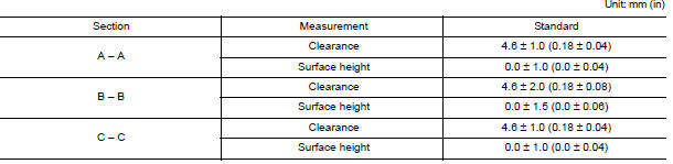
ADJUSTMENT PROCEDURE
- Remove front fender. Refer to DLK "FRONT FENDER : Removal and Installation".
- Loosen door hinge nuts on door side.
- Adjust the surface height of front door according to the specifications provided.
- Temporarily tighten door hinge nuts on door side.
- Loosen door hinge bolts on body side.
- Raise or lower the front door at rear end to adjust clearance of the front door according to the specifications provided.
- After adjustment tighten bolts and nuts to the specified torque.
CAUTION:
Check door hinge rotating point for poor lubrication. If necessary, apply a suitable multi-purpose grease.
After adjusting, apply touch-up paint (body color) onto the heads of hinge bolts and nuts.
8. Install front fender. Refer to refer to DLK "FRONT FENDER : Removal and Installation".
DOOR STRIKER ADJUSTMENT
Adjust door striker so that it becomes parallel with door lock insertion direction.
DOOR STRIKER
DOOR STRIKER : Removal and Installation
REMOVAL
Remove striker bolts and front door striker.
INSTALLATION
Installation is in the reverse order of removal.
CAUTION:
- After installation, check front door open/close, lock/unlock operation.
- After installation, perform the front door adjustment procedure. Refer to DLK "DOOR ASSEMBLY : Adjustment".
 Fender cover
FENDER COVER : Removal and Installation REMOVAL 1. Fully open hood assembly. 2. Disengage pawls beginning at the front of the fender cover and working toward the rear of vehicle and then remove fr ...
Door hinge
DOOR HINGE : Removal and Installation REMOVAL CAUTION: Use two people when removing or installing front door due to its heavy weight When removing and installing front door assembly, supp ...
Other materials:
Oil filter
Removal and Installation
REMOVAL
Remove engine under cover.
Drain engine oil.
Remove oil filter using Tool (A).
: Front
Tool number : KV10115801 (J38956)
WARNING:
Be careful not to get burned; engine and engine oil may be
hot.
CAUTION:
When removing, prepare a shop cl ...
A/T Control system
A/T Control system : component parts location
1. IPDM E/R 2. TCM 3. Transmission range switch
4. A/T unit 5. Output speed sensor 6. Stop lamp switch
7. A/T shift selector 8. Overdrive control switch 9. Combination meter (type B)
A/T Control system : component description
Name
...
Categories
- Manuals Home
- Nissan Versa Owners Manual
- Nissan Versa Service Manual
- Video Guides
- Questions & Answers
- External Resources
- Latest Updates
- Most Popular
- Sitemap
- Search the site
- Privacy Policy
- Contact Us

0.0091