Nissan Versa (N17): Door lock actuator
Driver side
DRIVER SIDE : Component Function Check
1.CHECK FUNCTION
- Select DOOR LOCK of BCM using CONSULT.
- Select DOOR LOCK in ACTIVE TEST mode.
- Touch ALL LOCK or ALL UNLK to check that it works normally.
Is the inspection result normal?
YES >> Door lock actuator is OK.
NO >> Refer to DLK "DRIVER SIDE : Diagnosis Procedure".
DRIVER SIDE : Diagnosis Procedure
Regarding Wiring Diagram information, refer to DLK "POWER DOOR LOCK SYSTEM : Wiring Diagram".
1.CHECK DOOR LOCK ACTUATOR INPUT SIGNAL
- Turn ignition switch OFF.
- Disconnect front door lock actuator LH connector.
- Check voltage between front door lock actuator LH harness connector and
ground.
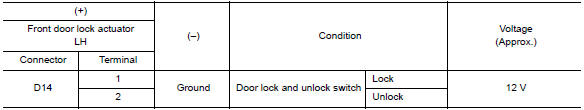
Is the inspection result normal?
YES >> Replace front door lock actuator LH .
NO >> GO TO 2.
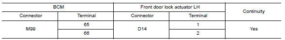
2.CHECK DOOR LOCK ACTUATOR CIRCUIT
- Disconnect BCM connector and all door lock actuator connectors.
- Check continuity between BCM harness connector and front door lock
actuator LH harness connector.
- Check continuity between BCM harness connector and ground.
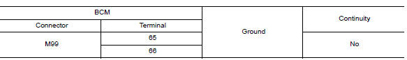
Is the inspection result normal?
YES >> GO TO 3.
NO >> Repair or replace harness.
3.CHECK BCM OUTPUT SIGNAL
- Connect BCM connector.
- Check voltage between front door lock actuator LH harness connector and
ground.
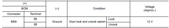
Is the inspection result normal?
YES >> Check for internal short of each door lock actuator.
NO >> Replace BCM. Refer to BCS "Removal and Installation".
Passenger side
PASSENGER SIDE : Component Function Check
1.CHECK FUNCTION
- Select DOOR LOCK of BCM using CONSULT.
- Select DOOR LOCK in ACTIVE TEST mode.
- Touch ALL LOCK or ALL UNLK to check that it works normally.
Is the inspection result normal?
YES >> Door lock actuator is OK.
NO >> Refer to DLK "PASSENGER SIDE : Diagnosis Procedure".
PASSENGER SIDE : Diagnosis Procedure
Regarding Wiring Diagram information, refer to DLK "POWER DOOR LOCK SYSTEM : Wiring Diagram".
1.CHECK DOOR LOCK ACTUATOR INPUT SIGNAL
- Turn ignition switch OFF.
- Disconnect front door lock actuator RH connector.
- Check voltage between front door lock actuator RH harness connector and
ground.
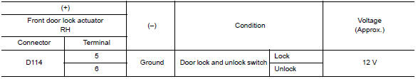
Is the inspection result normal?
YES >> Replace front door lock actuator (RH).
NO >> GO TO 2.
2.CHECK DOOR LOCK ACTUATOR CIRCUIT
- Disconnect BCM connector and all door lock actuators.
- Check continuity between BCM harness connector and front door lock
actuator RH harness connector.
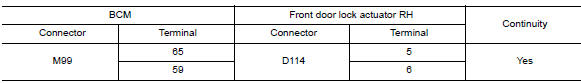
- Check continuity between BCM harness connector and ground.
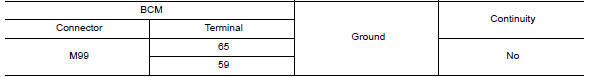
Is the inspection result normal?
YES >> GO TO 3.
NO >> Repair or replace harness.
3.CHECK BCM OUTPUT SIGNAL
- Connect BCM connector.
- Check voltage between front door lock actuator RH harness connector and
ground.
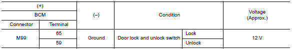
Is the inspection result normal?
YES >> Check for internal short of each door lock actuator.
NO >> Replace BCM. Refer to BCS "Removal and Installation".
 Combination meter buzzer
Component Function Check 1.CHECK FUNCTION Select INTELLIGENT KEY of BCM using CONSULT. Select INSIDE BUZZER in ACTIVE TEST mode. Touch Key, Knob or Take Out to check that it works normally. ...
Rear LH
REAR LH : Component Function Check 1.CHECK FUNCTION Select DOOR LOCK of BCM using CONSULT. Select DOOR LOCK in ACTIVE TEST mode. Touch ALL LOCK or ALL UNLK to check that it works normally. ...
Other materials:
Recommended fluids/lubricants and capacities
The following are approximate capacities. The actual refill capacities may
be a little different. When refilling, follow the procedure
described in the "Do-it-yourself" section to determine the proper refill
capacity.
...
EVAP canister vent control valve
Exploded View
1. EVAP canister 2. O-ring 3. EVAP canister vent control valve
4. EVAP canister vent control valve hose
Removal and Installation
NOTE:
The EVAP canister vent control valve can be removed without removing the EVAP
canister.
REMOVAL
Remove the EVAP canister protector cov ...
Categories
- Manuals Home
- Nissan Versa Owners Manual
- Nissan Versa Service Manual
- Video Guides
- Questions & Answers
- External Resources
- Latest Updates
- Most Popular
- Sitemap
- Search the site
- Privacy Policy
- Contact Us

0.0057