Nissan Versa (N17): Door lock actuator
Driver side
DRIVER SIDE : Description
Locks/unlocks the door with the signal from BCM.
DRIVER SIDE : Component Function Check
1.CHECK FUNCTION
- Use CONSULT to perform Active Test ("DOOR LOCK").
- Touch "ALL LOCK" or "ALL UNLOCK" to check that it works normally.
Is the inspection result normal?
YES >> Door lock actuator is OK.
NO >> Refer to DLK "DRIVER SIDE : Diagnosis Procedure".
DRIVER SIDE : Diagnosis Procedure
Regarding Wiring Diagram information, refer to DLK "Wiring Diagram".
1.CHECK OUTPUT SIGNAL
Check voltage between BCM connector and ground. 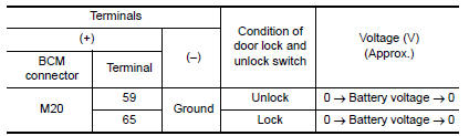
Is the inspection result normal?
YES >> GO TO 3
NO >> GO TO 2
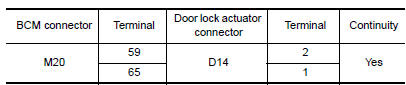
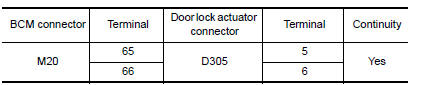
2.CHECK DOOR LOCK ACTUATOR CIRCUIT
- Turn ignition switch OFF.
- Disconnect BCM and front door lock actuator driver side connector.
- Check continuity between BCM connector and front door lock actuator
driver side connector.
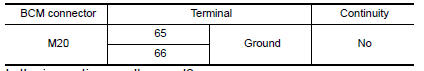
- Check continuity between BCM connector and ground.
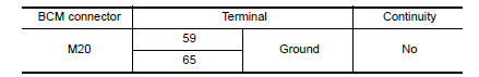
Is the inspection result normal?
YES >> Replace front door lock actuator LH.
NO >> Repair or replace harness.
3.CHECK INTERMITTENT INCIDENT
Refer to GI "Intermittent Incident".
>> Inspection End.
Passenger side
PASSENGER SIDE : Description
Locks/unlocks the door with the signal from BCM.
PASSENGER SIDE : Component Function Check
1.CHECK FUNCTION
- Use CONSULT to perform Active Test ("DOOR LOCK").
- Touch "ALL LOCK" or "ALL UNLOCK" to check that it works normally.
Is the inspection result normal?
YES >> Door lock actuator is OK.
NO >> Refer to DLK "PASSENGER SIDE : Diagnosis Procedure".
PASSENGER SIDE : Diagnosis Procedure
Regarding Wiring Diagram information, refer to DLK "Wiring Diagram".
1.CHECK DOOR LOCK ACTUATOR SIGNAL
Check voltage between BCM connector and ground. 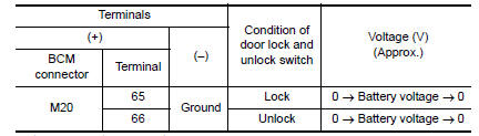
Is the inspection result normal?
YES >> GO TO 3
NO >> GO TO 2
2.CHECK DOOR LOCK ACTUATOR CIRCUIT
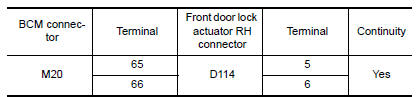
- Disconnect BCM and front door lock actuator RH connectors.
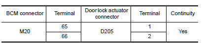
- Check continuity between BCM connector and front door lock actuator RH.
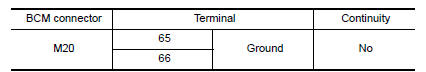
- Check continuity between BCM connector and ground.
Is the inspection result normal?
YES >> Replace front door lock actuator RH.
NO >> Repair or replace harness.
3.CHECK INTERMITTENT INCIDENT
Refer to GI "Intermittent Incident".
>> Inspection End.
Rear LH
REAR LH : Description
Locks/unlocks the door with the signal from BCM.
REAR LH : Component Function Check
1.CHECK FUNCTION
- Use CONSULT to perform Active Test ("DOOR LOCK").
- Touch "ALL LOCK" or "ALL UNLOCK" to check that it works normally.
Is the inspection result normal?
YES >> Door lock actuator is OK.
NO >> Refer to DLK "REAR LH : Diagnosis Procedure".
REAR LH : Diagnosis Procedure
Regarding Wiring Diagram information, refer to DLK "Wiring Diagram".
1.CHECK DOOR LOCK ACTUATOR SIGNAL
Check voltage between BCM connector and ground. 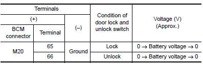
Is the inspection result normal?
YES >> GO TO 3
NO >> GO TO 2
2.CHECK DOOR LOCK ACTUATOR CIRCUIT
- Disconnect BCM and rear door lock actuator LH connectors.
- Check continuity between BCM connector and rear door lock actuator LH
connectors.
- Check continuity between BCM connector and ground.


Is the inspection result normal?
YES >> Replace rear door lock actuator LH.
NO >> Repair or replace harness.
3.CHECK INTERMITTENT INCIDENT
Refer to GI "Intermittent Incident".
>> Inspection End.
Rear RH
REAR RH : Description
Locks/unlocks the door with the signal from BCM.
REAR RH : Component Function Check
1.CHECK FUNCTION
- Use CONSULT to perform Active Test ("DOOR LOCK").
- Touch "ALL LOCK" or "ALL UNLOCK" to check that it works normally.
Is the inspection result normal?
YES >> Door lock actuator is OK.
NO >> Refer to DLK "REAR RH : Diagnosis Procedure".
REAR RH : Diagnosis Procedure
Regarding Wiring Diagram information, refer to DLK "Wiring Diagram".
1.CHECK DOOR LOCK ACTUATOR SIGNAL
Check voltage between BCM connector and ground. 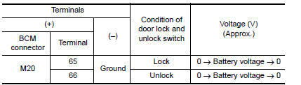
Is the inspection result normal?
YES >> GO TO 3
NO >> GO TO 2
2.CHECK DOOR LOCK ACTUATOR CIRCUIT
- Disconnect BCM and rear door lock actuator RH connectors.
- Check continuity between BCM connector and rear door lock actuator RH
connectors.
- Check continuity between BCM connector and ground.
Is the inspection result normal?
YES >> Replace rear door lock actuator RH.
NO >> Repair or replace harness.
3.CHECK INTERMITTENT INCIDENT
Refer to GI "Intermittent Incident".
>> Inspection End.
 Key switch (BCM Input)
Diagnosis Procedure Regarding Wiring Diagram information, refer to DLK "Wiring Diagram". 1.CHECK KEY SWITCH INPUT SIGNAL With CONSULT Check k ...
Trunk lid opener actuator
Component Function Check 1.CHECK FUNCTION Press the trunk release button on the keyfob and check that the trunk lid opens. Is the inspection result normal? YES >> Inspection End. NO > ...
Other materials:
NISSAN Voice Recognition System (if so equipped)
The NISSAN Voice Recognition system allows
hands-free operation of the systems equipped on
this vehicle, such as the phone and navigation
systems.
To operate NISSAN Voice Recognition, press
the button located on the steering
wheel.
When prompted, speak the command for the
system you wi ...
Spark plugs
Replacing spark plugs
Platinum-tipped spark plugs
It is not necessary to replace platinum-tipped A
spark plugs as frequently as conventional type
spark plugs because they last much longer. Follow
the maintenance log shown in the Maintenance
and Schedules section of this manual. Do
not ser ...
Categories
- Manuals Home
- Nissan Versa Owners Manual
- Nissan Versa Service Manual
- Video Guides
- Questions & Answers
- External Resources
- Latest Updates
- Most Popular
- Sitemap
- Search the site
- Privacy Policy
- Contact Us

0.0071