
Nissan Versa (N17): Key switch (BCM Input)
Diagnosis Procedure
Regarding Wiring Diagram information, refer to DLK "Wiring Diagram".
1.CHECK KEY SWITCH INPUT SIGNAL
With CONSULT
Check key switch "KEY ON SW" in DATA MONITOR mode with CONSULT. Refer to BCS "DOOR LOCK : CONSULT Function (BCM - DOOR LOCK)".
- When key is inserted to ignition key cylinder:
KEY ON SW : ON
- When key is removed from ignition key cylinder:
KEY ON SW : OFF
Without CONSULT
Check voltage between BCM connector M18 terminal 37 and ground. 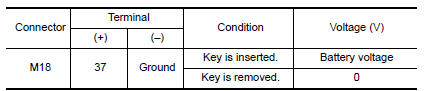
Is the inspection result normal?
YES >> Key switch (insert) circuit is OK.
NO >> GO TO 2
2.CHECK KEY SWITCH (INSERT)
- Turn ignition switch OFF.
- Disconnect key switch connector.
- Check continuity between key switch terminals.

Is the inspection result normal?
YES >> Repair or replace harness or fuse.
NO >> Replace key switch.
 Key cylinder switch
Description When the mechanical key is inserted and turned into the front door lock key cylinder switch LH, the switch transmits the LOCK or UNLOCK signal directly to the BCM. ...

Other materials:
4-speed automatic transmission fluid (ATF) (if so equipped)
When checking or replacement of automatic
transmission fluid is required, it is recommended
that you visit a NISSAN dealer for servicing.
WARNING
When the engine is running, keep
hands, jewelry and clothing away from
any moving parts such as the cooling
fan and drive belts
Automatic t ...
Preparation
Special Service Tools
The actual shapes of KentMoore tools may differ from those of special
service tools illustrated here.
Tool number
(KentMoore No.)
Tool name
Description
ST25051001
(J256951)
Oil pressure gauge &nbs ...
Categories
- Manuals Home
- Nissan Versa Owners Manual
- Nissan Versa Service Manual
- Video Guides
- Questions & Answers
- External Resources
- Latest Updates
- Most Popular
- Sitemap
- Search the site
- Privacy Policy
- Contact Us

0.0072