Nissan Versa (N17): Door lock and unlock switch
DRIVER SIDE
DRIVER SIDE : Description
Transmits door lock/unlock operation to BCM.
DRIVER SIDE : Component Function Check
1.CHECK FUNCTION
With CONSULT
Check CDL LOCK SW, CDL UNLOCK SW in Data Monitor mode with CONSULT. 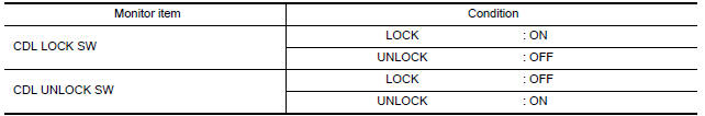
Is the inspection result normal?
YES >> Door lock and unlock switch is OK.
NO >> Refer to DLK "DRIVER SIDE : Diagnosis Procedure".
DRIVER SIDE : Diagnosis Procedure
Regarding Wiring Diagram information, refer to DLK "Wiring Diagram".
1.CHECK POWER WINDOW SWITCH OUTPUT SIGNAL
- Turn ignition switch ON.
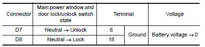
- Check voltage at the main power window and door lock/unlock switch
connector when the switch (driver
side) is turned to "LOCK" or "UNLOCK".
Is the inspection result normal?
YES >> GO TO 5
NO >> GO TO 2
2.CHECK POWER WINDOW SWITCH GROUND
- Turn ignition switch OFF.
- Disconnect main power window and door lock/unlock switch connector.
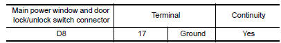
- Check continuity between main power window and door lock/unlock switch
connector and ground.
Is the inspection result normal?
YES >> GO TO 3
NO >> Repair or replace harness.
3.CHECK POWER WINDOW SWITCH
Check continuity between main power window and door lock/unlock switch
terminals. 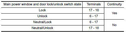
Is the inspection result normal?
YES >> GO TO 4
NO >> Replace main power window and door lock/unlock switch. Refer to DLK "Removal and Installation".
4.CHECK POWER WINDOW SWITCH CIRCUITS
- Disconnect BCM connector.
- Check continuity between BCM connector and main power window and door
lock/unlock switch connector.
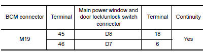
- Check continuity between BCM connector and ground.
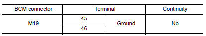
Is the inspection result normal?
YES >> GO TO 5
NO >> Repair or replace harness.
5.CHECK INTERMITTENT INCIDENT
Refer to GI "Intermittent Incident".
>> Inspection End.
PASSENGER SIDE
PASSENGER SIDE : Description
Transmits door lock/unlock operation to BCM.
PASSENGER SIDE : Component Function Check
1.CHECK FUNCTION
With CONSULT
Check CDL LOCK SW, CDL UNLOCK SW in Data Monitor mode with CONSULT. 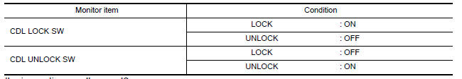
Is the inspection result normal?
YES >> Door lock and unlock switch is OK.
NO >> Refer to DLK "PASSENGER SIDE : Diagnosis Procedure".
PASSENGER SIDE : Diagnosis Procedure
Regarding Wiring Diagram information, refer to DLK "Wiring Diagram".
1.CHECK POWER WINDOW SWITCH OUTPUT SIGNAL
- Turn ignition switch ON.
- Check voltage at the power window and door lock/unlock switch RH
connector when the switch (passenger
side) is turned to "LOCK" or "UNLOCK".
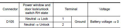
Is the inspection result normal?
YES >> GO TO 5
NO >> GO TO 2
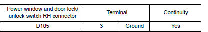
2.CHECK POWER WINDOW SWITCH GROUND
- Turn ignition switch OFF.
- Disconnect power window and door lock/unlock switch RH connector.
- Check continuity between power window and door lock/unlock switch RH
connector and ground.
Is the inspection result normal?
YES >> GO TO 3
NO >> Repair or replace harness.
3.CHECK POWER WINDOW SWITCH
Check continuity between power window and door lock/unlock switch RH
terminals. 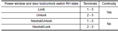
Is the inspection result normal?
YES >> GO TO 4
NO >> Replace power window and door lock/unlock switch RH.
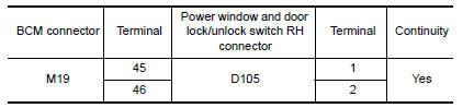
4.CHECK POWER WINDOW SWITCH CIRCUITS
- Disconnect BCM connector.
- Check continuity between BCM connector and power window and door
lock/unlock switch RH connector.
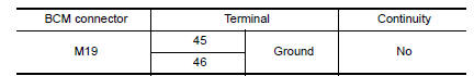
- Check continuity between BCM connector and ground.
Is the inspection result normal?
YES >> GO TO 5
NO >> Repair or replace harness.
5.CHECK INTERMITTENT INCIDENT
Refer to GI "Intermittent Incident".
>> Inspection End.
 Door switch
Description Detects door open/close condition. ...
Key cylinder switch
Description When the mechanical key is inserted and turned into the front door lock key cylinder switch LH, the switch transmits the LOCK or UNLOCK signal directly to the BCM. ...
Other materials:
Hood
1. Pull the hood lock release handle 1 located
below the instrument panel until the hood
springs up slightly.
2. Locate the lever 2 in between the hood and
grille and push the lever sideways with your
fingertips.
3. Raise the hood 3 .
4. Remove the support rod and insert it into the
...
Steering wheel
Tilt operation
Push the lock lever 1 down and adjust the
steering wheel up or down 2 to the desired
position.
Pull the lock lever 1 up to lock the steering
wheel in place.
WARNING
Do not adjust the steering wheel while
driving. You could lose control of your
vehicle and cause an accid ...
Categories
- Manuals Home
- Nissan Versa Owners Manual
- Nissan Versa Service Manual
- Video Guides
- Questions & Answers
- External Resources
- Latest Updates
- Most Popular
- Sitemap
- Search the site
- Privacy Policy
- Contact Us

0.0071