Nissan Versa (N17): DTC B2205 Vehicle speed circuit
Description
The ABS actuator and electric unit (control unit) provides a vehicle speed signal to the combination meter via CAN communication lines.
DTC Logic
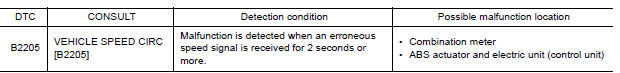
Diagnosis Procedure
1.CHECK COMBINATION METER INPUT SIGNAL
1. Start engine and select METER/M&A on CONSULT.
2. Using SPEED METER on DATA MONITOR, compare the DATA MONITOR value with the combination meter speedometer. Speedometer and DATA MONITOR indications should be close.
Is the inspection result normal?
YES >> Perform ABS actuator and electric unit (control unit) self-diagnosis. Refer to BRC "CONSULT Function (ABS)".
NO >> Replace combination meter. Refer to MWI "Removal and Installation".
 U1000 CAN Comm circuit
DTC Logic DTC DETECTION LOGIC Diagn ...
B2267 Engine speed
Description The engine speed signal is transmitted from ECM to the combination meter via CAN communication. DTC Logic DTC DETECTION LOGIC &n ...
Other materials:
Gear oil
Inspection
OIL LEAKAGE
Make sure that gear oil is not leaking from transaxle or around it.
OIL LEVEL
Remove filler plug (1) and gasket from transaxle case.
Check the oil level from filler plug hole as shown. CAUTION:
Do not start engine while checking oil level.
Install a new gas ...
Additional service when replacing
transaxle assembly
Description
Perform the following work after the transaxle assembly is replaced.
ERASING AND LOADING OF THE CALIBRATION DATA
The TCM acquires calibration data (individual characteristic value) of
each solenoid that is stored in the
ROM assembly (in the control valve). This enables the TCM ...
Categories
- Manuals Home
- Nissan Versa Owners Manual
- Nissan Versa Service Manual
- Video Guides
- Questions & Answers
- External Resources
- Latest Updates
- Most Popular
- Sitemap
- Search the site
- Privacy Policy
- Contact Us

0.0048