Nissan Versa (N17): P0713 Transmission fluid temperature sensor A
DTC Logic
DTC DETECTION LOGIC
| DTC | Trouble diagnosis name | DTC detection condition | Possible causes |
| P0713 | Transmission Fluid Temperature Sensor A Circuit High | The CVT fluid temperature identified by the
TCM is −40C (−40F) or less continuously for
5 seconds or more under the following diagnosis
conditions: - Diagnosis conditions - Ignition switch: ON - Vehicle speed: More than 10 km/h (7 MPH) - TCM power supply voltage: More than 11 V |
- Harness or connector
(CVT fluid temperature sensor circuit is
open or shorted to power supply) - CVT fluid temperature sensor |
DTC CONFIRMATION PROCEDURE
1.PREPARATION BEFORE WORK
If another "DTC CONFIRMATION PROCEDURE" occurs just before, turn ignition switch OFF and wait for at least 10 seconds, then perform the next test.
>> GO TO 2.
2.PERFORM DTC CONFIRMATION PROCEDURE
- Start the engine.
- Maintain the following condition for 10 seconds or more.
- Stop the vehicle.
- Check the first trip DTC.
Vehicle speed : 20 km/h (12 MPH) or more
Is "P0713" detected?
YES >> Go to TM "Diagnosis Procedure".
NO >> INSPECTION END
Diagnosis Procedure
1.CHECK CIRCUIT BETWEEN TCM AND CVT UNIT (PART 1)
- Turn ignition switch OFF.
- Disconnect TCM connector and CVT unit connector.
- Check continuity between TCM harness connector terminals and CVT unit
harness connector terminals.
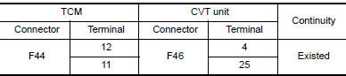
Is the inspection result normal?
YES >> GO TO 2.
NO >> Repair or replace malfunctioning part.
2.CHECK CIRCUIT BETWEEN TCM AND CVT UNIT (PART 2)
- Turn ignition switch ON.
- Check voltage between TCM harness connector terminal and ground.
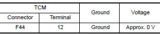
Is the inspection result normal?
YES >> GO TO 3.
NO >> Repair or replace malfunctioning part.
3.CHECK CVT FLUID TEMPERATURE SENSOR
Check CVT fluid temperature sensor. Refer to TM "Component Inspection (CVT Fluid Temperature Sensor)".
Is the inspection result normal?
YES >> Check intermittent incident. Refer to GI "Intermittent Incident".
NO >> Repair or replace malfunctioning parts.
Component Inspection (CVT Fluid Temperature Sensor)
1.CHECK CVT FLUID TEMPERATURE SENSOR
Check resistance between CVT unit connector terminals. 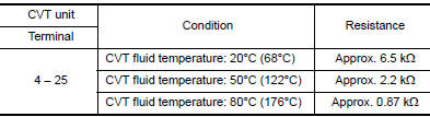
Is the inspection result normal?
YES >> INSPECTION END
NO >> There is a malfunction of CVT fluid temperature sensor. Replace transaxle assembly. Refer to TM "Removal and Installation".
 P0712 Transmission fluid temperature
sensor A
P0712 Transmission fluid temperature
sensor A
DTC Logic DTC DETECTION LOGIC DTC Trouble diagnosis name DTC detection condition Possible causes P0712 Transmission Fluid Temperature Sensor A Circuit Low The CVT ...

Other materials:
Idle air volume learning
Description
Idle Air Volume Learning is a function of ECM to learn the idle air volume
that keeps each engine idle speed
within the specific range. It must be performed under any of the following
conditions:
Each time electric throttle control actuator or ECM is replaced.
Idle speed or ...
Structure and operation
Sectional View
1. Clutch housing 2. 1st-2nd synchronizer hub assembly 3. 3rd-4th
synchronizer hub assembly
4. 5th input gear 5. 5th-reverse synchronizer hub assembly 6. 5th-reverse baulk
ring
7. 5th main gear 8. 4th main gear 9. 3rd main gear
10. 2nd main gear 11. 2nd double-cone synchr ...
Categories
- Manuals Home
- Nissan Versa Owners Manual
- Nissan Versa Service Manual
- Video Guides
- Questions & Answers
- External Resources
- Latest Updates
- Most Popular
- Sitemap
- Search the site
- Privacy Policy
- Contact Us

0.006