Nissan Versa (N17): P0999 Shift solenoid F
DTC Logic
DTC DETECTION LOGIC
| DTC | Trouble diagnosis name | DTC detection condition | Possible causes |
| P0999 | Shift solenoid F control circuit high | The TCM low brake solenoid valve current
monitor reading is 200 mA or less continuously
for 200 msec or more under the following diagnosis
conditions: Diagnosis conditions - Solenoid valve output current: 750 mA or more - GND short diagnosis of the solenoid valve circuit is not satisfied. - TCM power supply voltage: More than 11 V |
- Harness or connector
(Low brake solenoid valve circuit is
open or shorted to power supply) - Low brake solenoid valve |
DTC CONFIRMATION PROCEDURE
1.PREPARATION BEFORE WORK
If another "DTC CONFIRMATION PROCEDURE" occurs just before, turn ignition switch OFF and wait for at least 10 seconds, then perform the next test.
>> GO TO 2.
2.CHECK DTC DETECTION
- Start the engine.
- Shift the selector lever to "D" position and wait for 5 seconds or more.
- Check the first trip DTC.
Is "P0999" detected?
YES >> Go to TM "Diagnosis Procedure".
NO >> INSPECTION END
Diagnosis Procedure
1.CHECK CIRCUIT BETWEEN TCM AND CVT UNIT
- Turn ignition switch OFF.
- Disconnect TCM connector and CVT unit connector.
- Check continuity between TCM harness connector terminal and CVT unit
harness connector terminal.
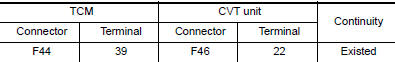
Is the inspection result normal?
YES >> GO TO 2.
NO >> Repair or replace malfunctioning parts.
2.CHECK LOW BRAKE SOLENOID VALVE
Check low brake solenoid valve. Refer to TM "Component Inspection (Low Brake Solenoid Valve)".
Is the inspection result normal?
YES >> Check intermittent incident. Refer to GI "Intermittent Incident".
NO >> Repair or replace malfunctioning parts.
Component Inspection (Low Brake Solenoid Valve)
1.CHECK LOW BRAKE SOLENOID VALVE
Check resistance between CVT unit connector terminal and ground. 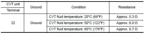
Is the inspection result normal?
YES >> INSPECTION END
NO >> There is a malfunction of low brake solenoid valve. Replace transaxle assembly. Refer to TM "Removal and Installation".
 P0998 Shift solenoid F
Other materials:
Heater and Air Conditioner (manual)
WARNING
The air conditioner cooling function operates
only when the engine is running.
Do not leave children or adults who
would normally require the assistance
of others alone in your vehicle. Pets
should also not be left alone. They
could accidentally injure themselves or
others ...
Water pump
Exploded View
1. Gasket 2. Water pump 3. Water pump pulley
Removal and Installation
REMOVAL
CAUTION:
Do not remove the radiator cap when the engine is hot. Serious burns
could occur from highpressure
engine coolant escaping from the radiator. Wrap a thick cloth around the
radiator cap. ...
Categories
- Manuals Home
- Nissan Versa Owners Manual
- Nissan Versa Service Manual
- Video Guides
- Questions & Answers
- External Resources
- Latest Updates
- Most Popular
- Sitemap
- Search the site
- Privacy Policy
- Contact Us

0.0053